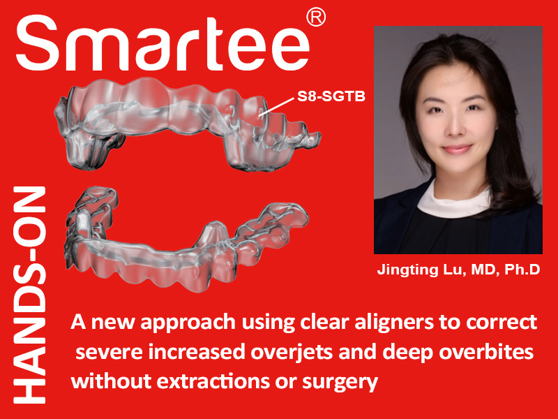
Hands-on Alineadores Smartee S8. Dr Lu. 9 Febrero 2023.
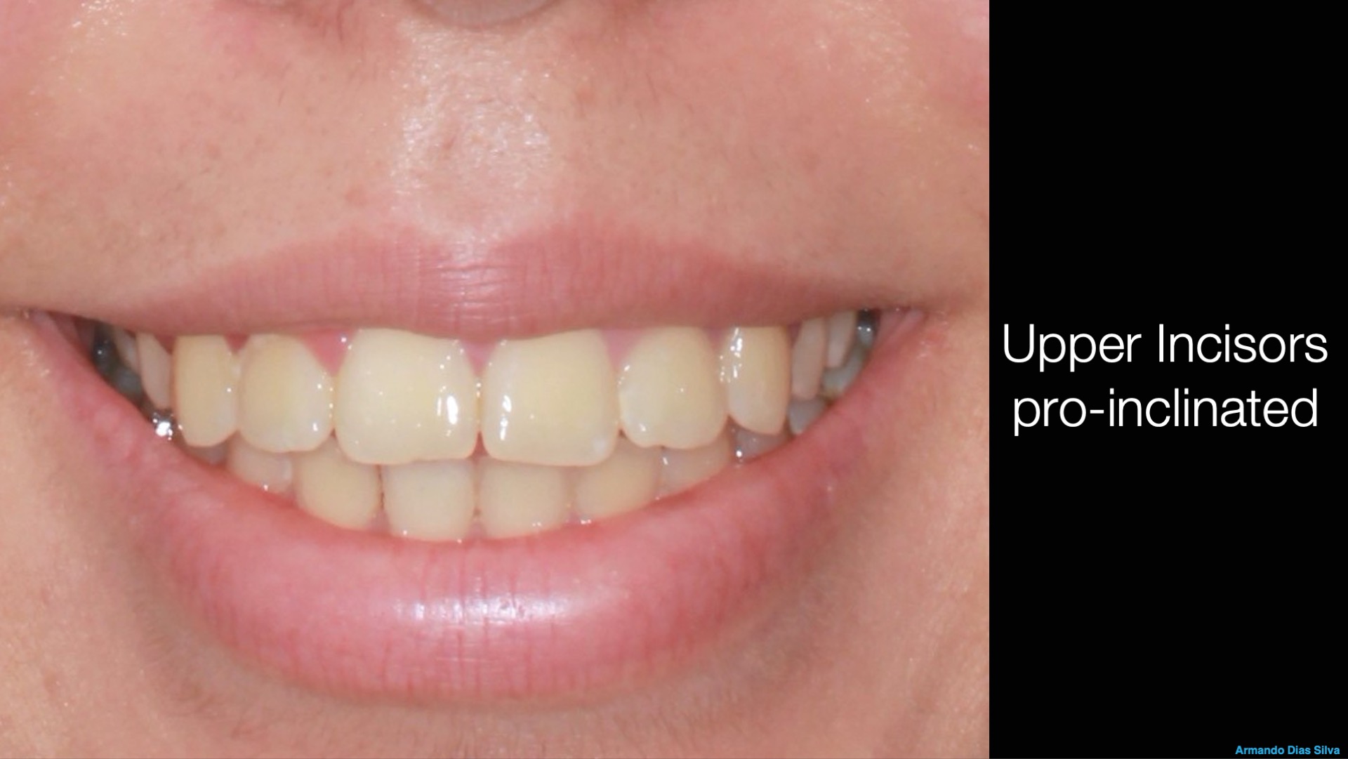
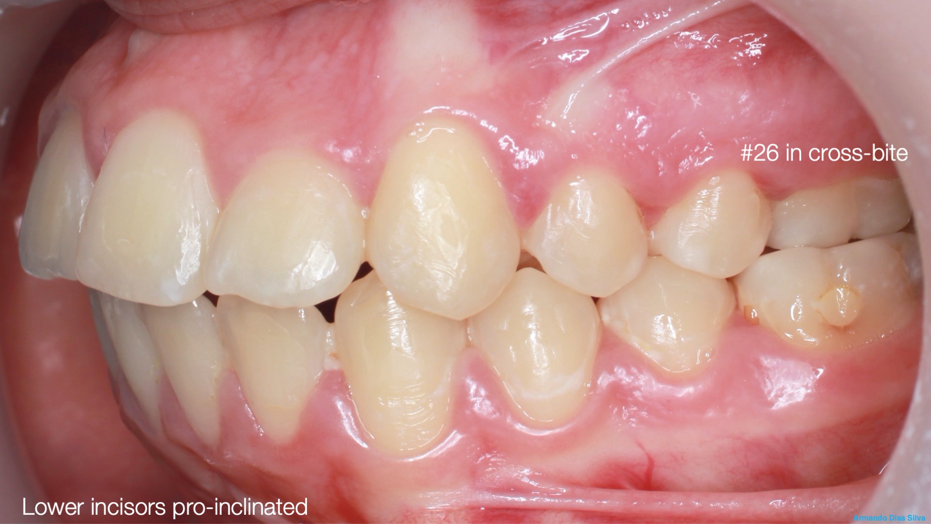
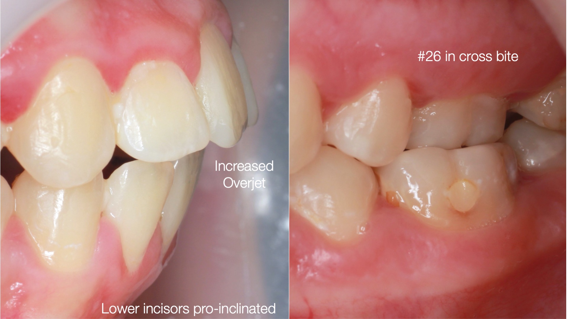
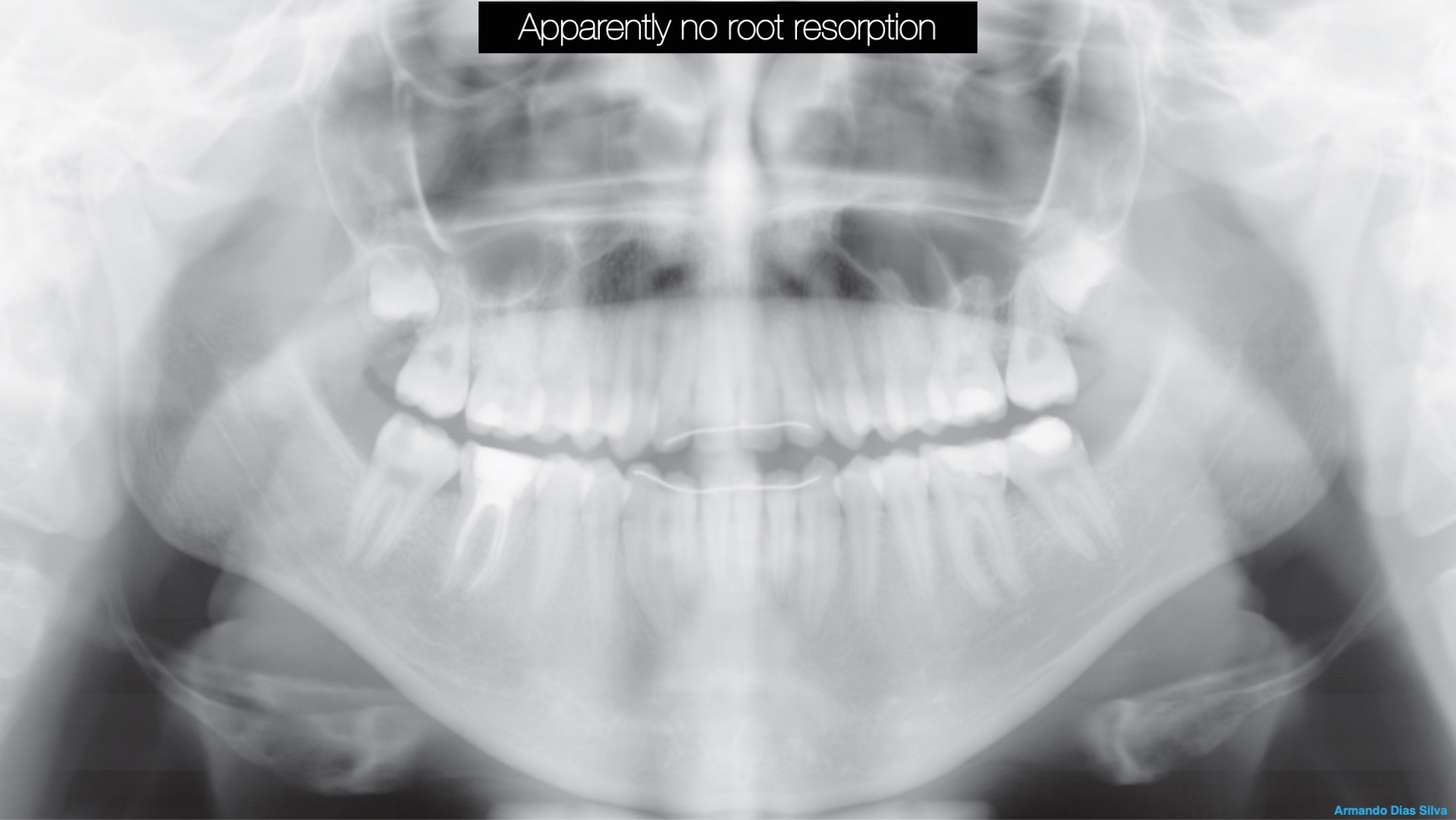
A new approach using clear aligners to correct severe increased oversets and deep overbites without extractions or surgery.
Dr. Jingting Lu
Fecha:
9 de Febrero de 2023
18:00 a 20:00 horas
Modalidad:
Práctica Hands-on
durante el Congreso Alignea en Ávila
Cupo: Limitado
Idioma:
Inglés con traducción
Lugar:
Palacio de Congresos de Ávila
Consultas Teléfono 96.342.0478
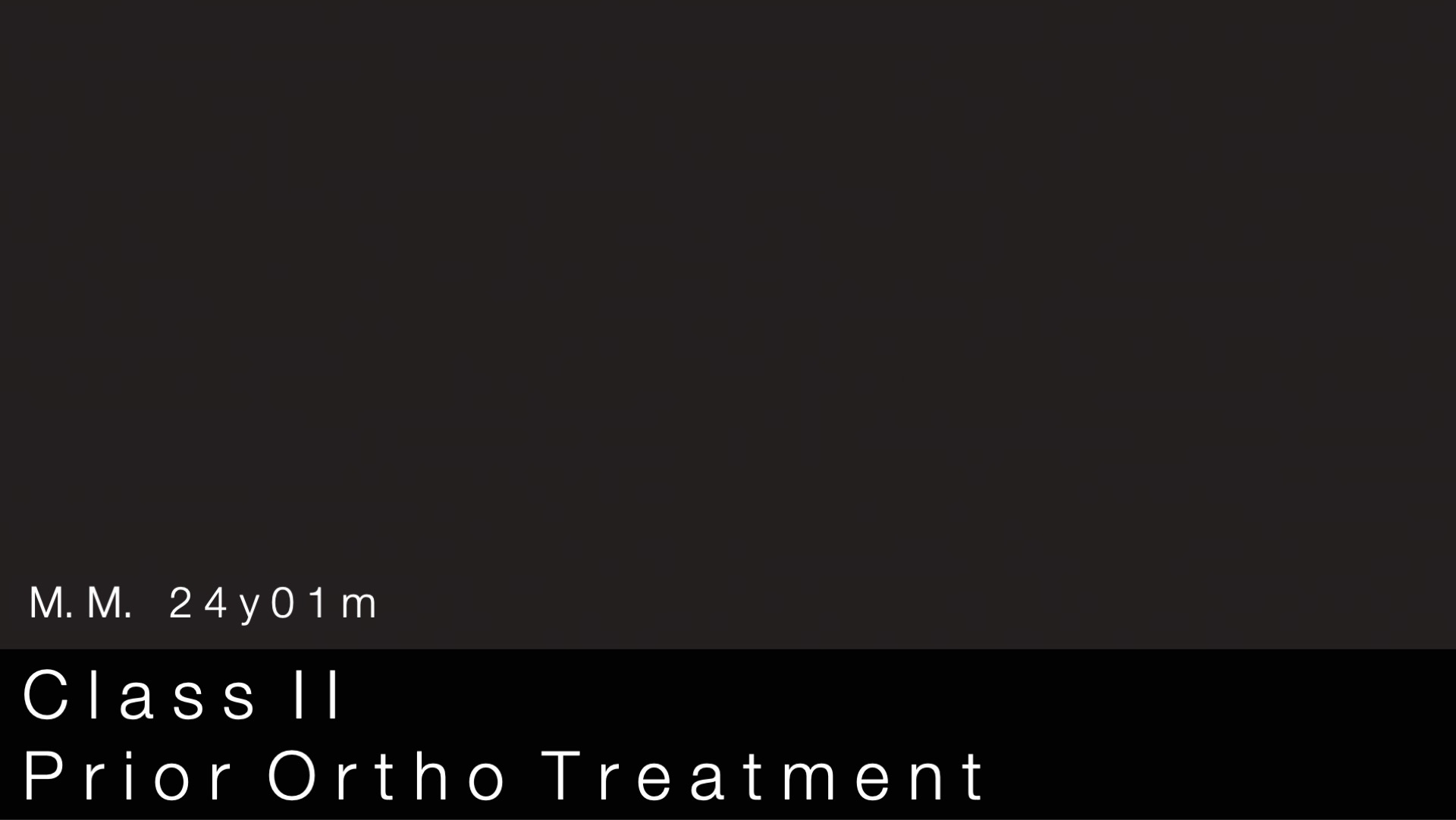
Explore the new era of trading Class II cases without extractions or surgery
A new approach using clear aligners to correct severe increased oversets and deep overbites without extractions or surgery.
Parte I: Conferencia
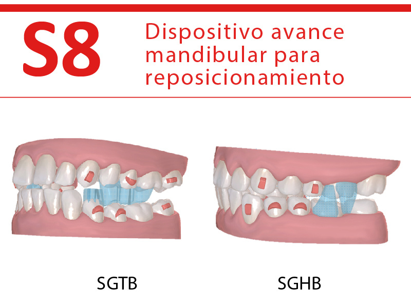
– What is the Smartee S8 mandibular repositioning technology?
– What type of cases can you treat with the Smartee S8?
– Effectively correcting increased oversets and deep overbites in patients with protrusive facial profiles without extractions or surgery
Parte II: Hands-on
– How to start your first Smartee GS case?
Dr. Jingting Lu MD, Ph.D,
-Shanghai Jiaotong University School of Medicine Senior Ortho Expert
-Dean of Shanghai Lujingting Dental Clinic
-Director of Department of Orthodontics, Dingzhi Dental
-Member of Shanghai Stomatological Association
-Member of Chinese Academy of Esthetic Dentistry

Te puede interesar...

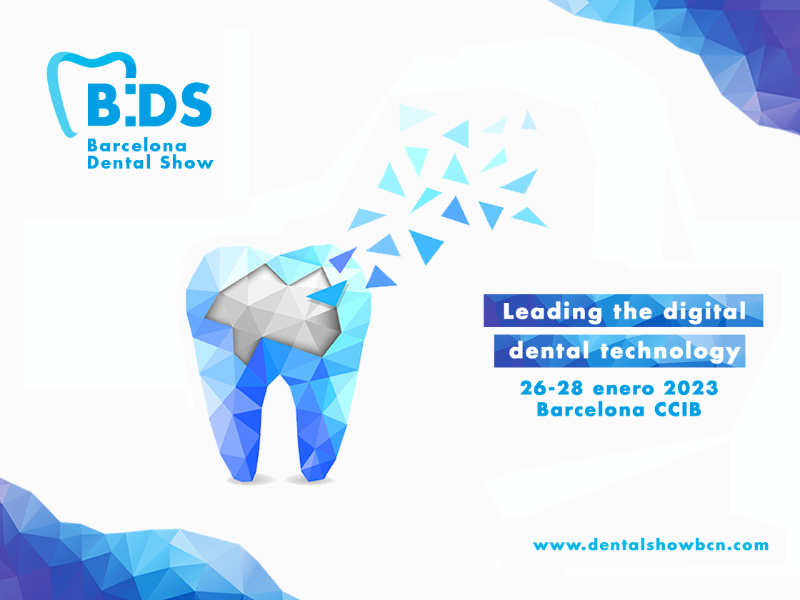
Barcelona Dental Show. 26-28 Enero-2023
Ven a conocer las novedades y aprovechar nuestras ofertas
Fecha: 26 al 28 de Enero de 2023
Lugar:
Centro de Convenciones Internacional de Barcelona
Plaza de Willy Brandt 11-14
08019 Barcelona
Visítanos!! Stand #D413
Barcelona Dental Show

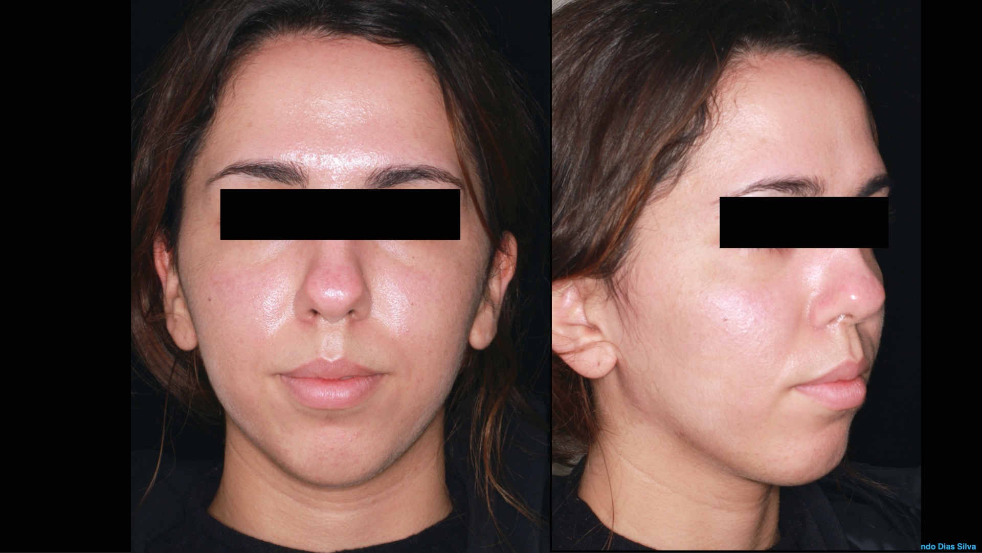
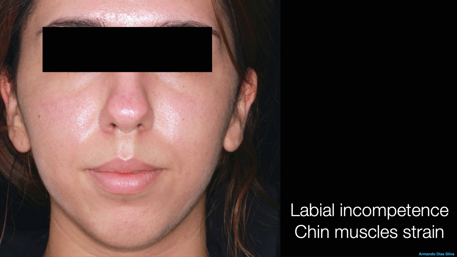
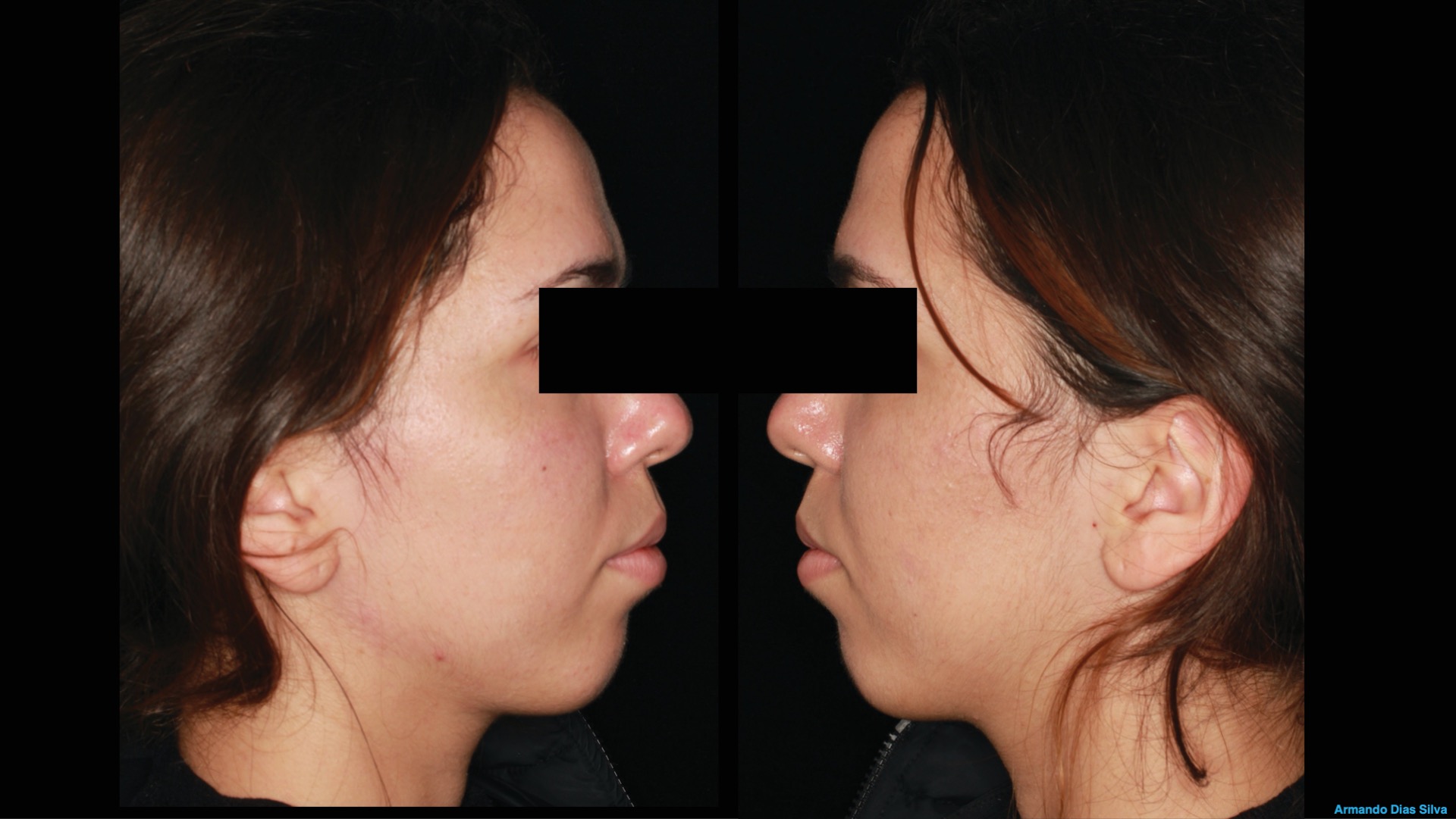
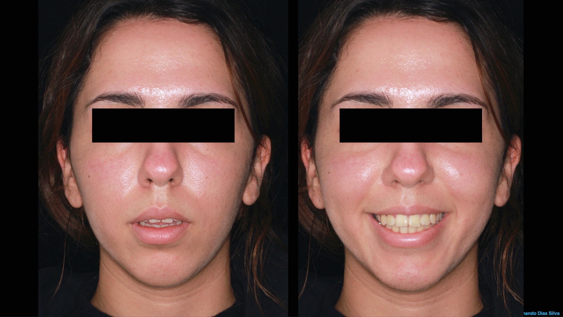
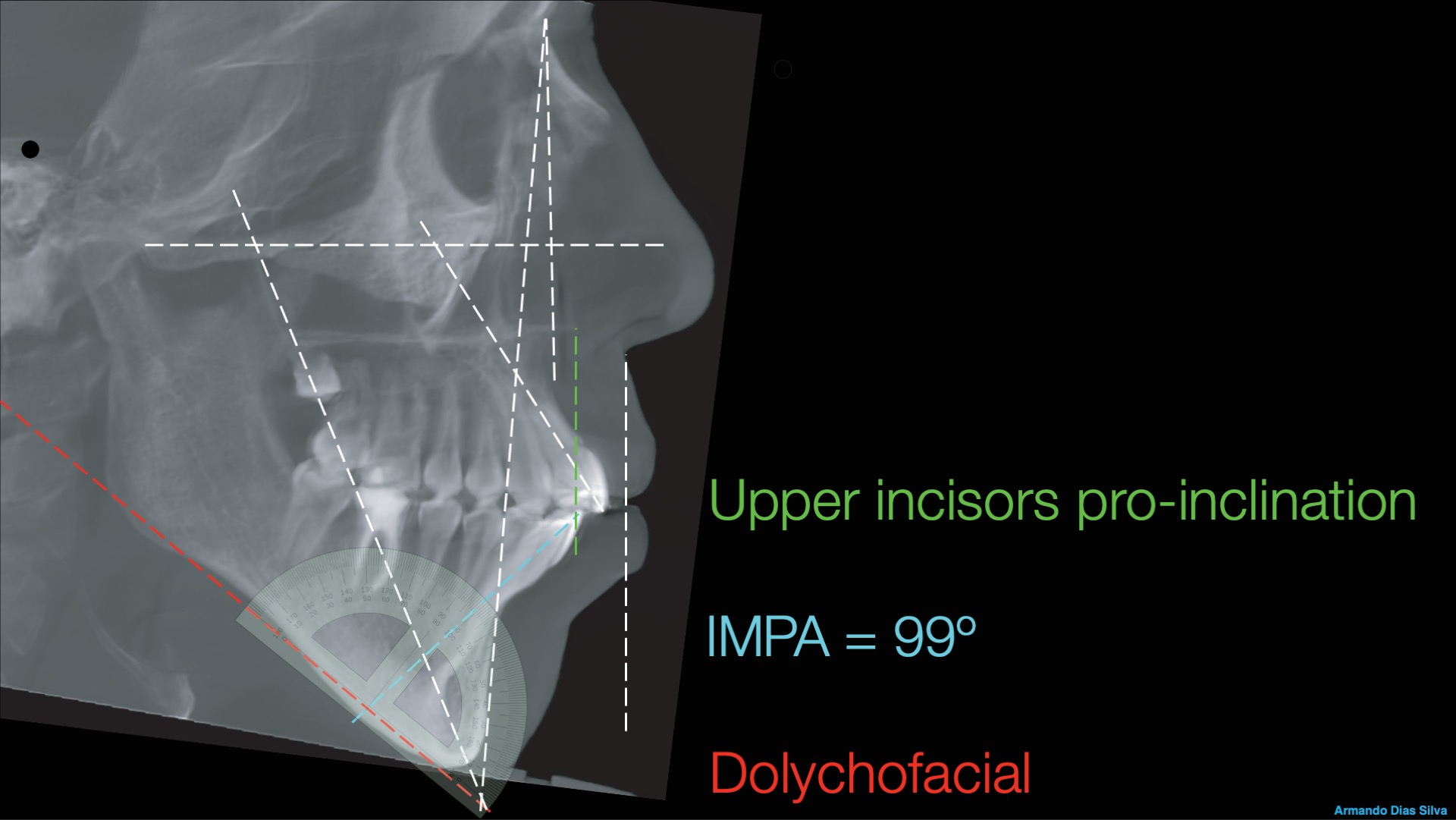
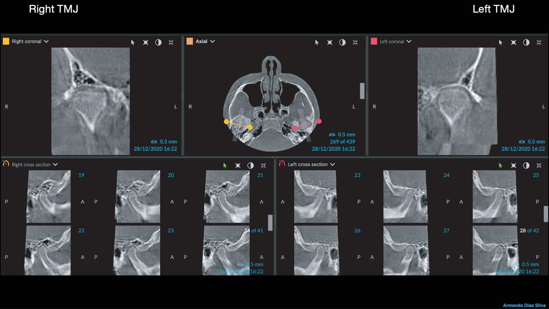
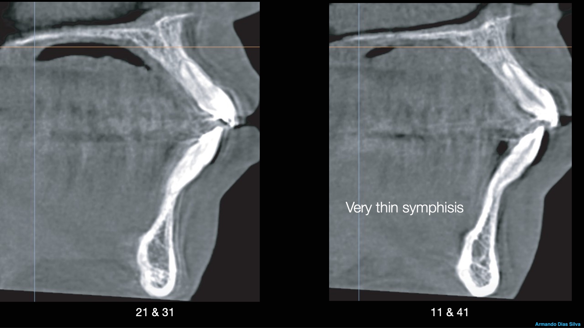
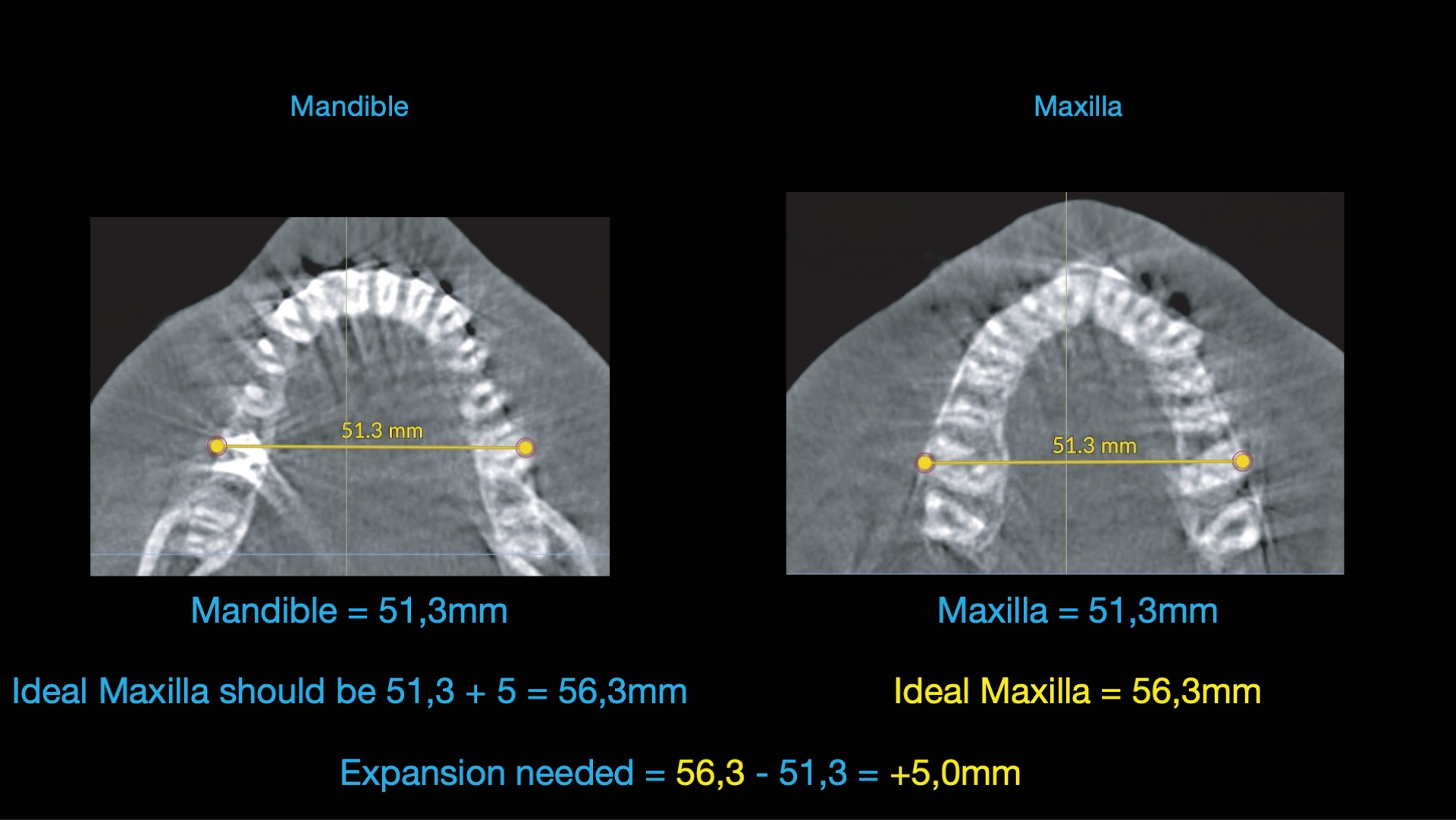
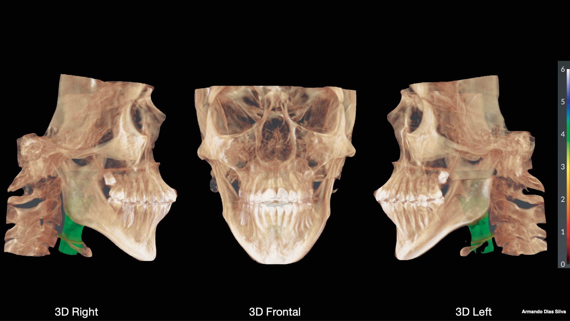
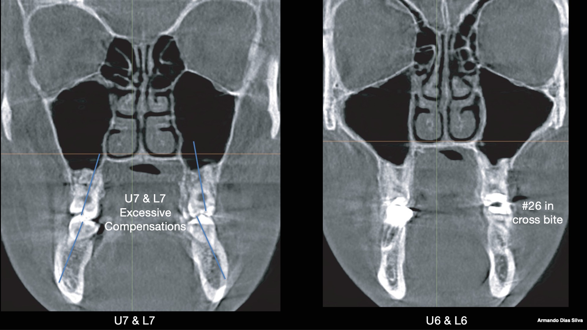
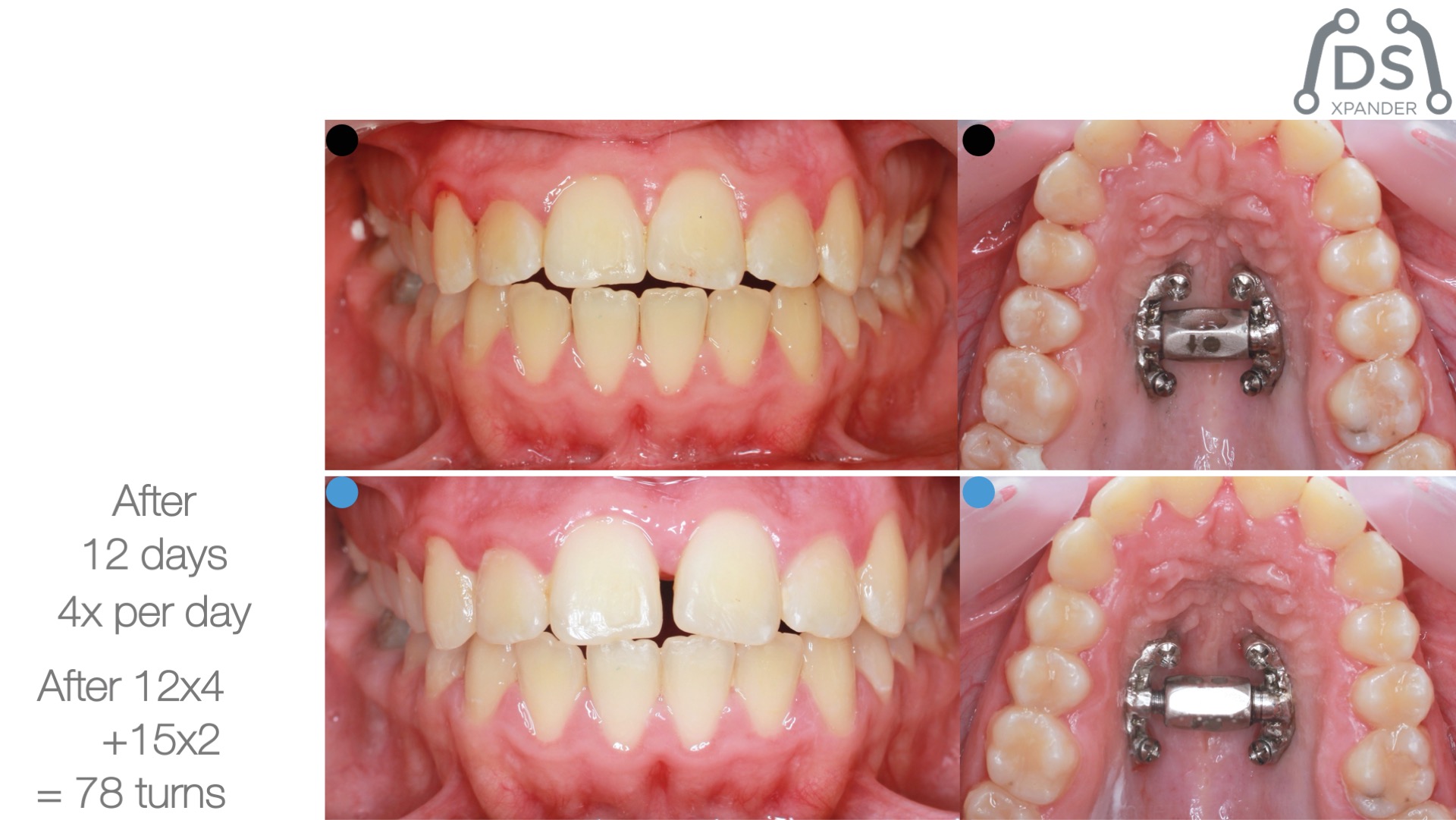
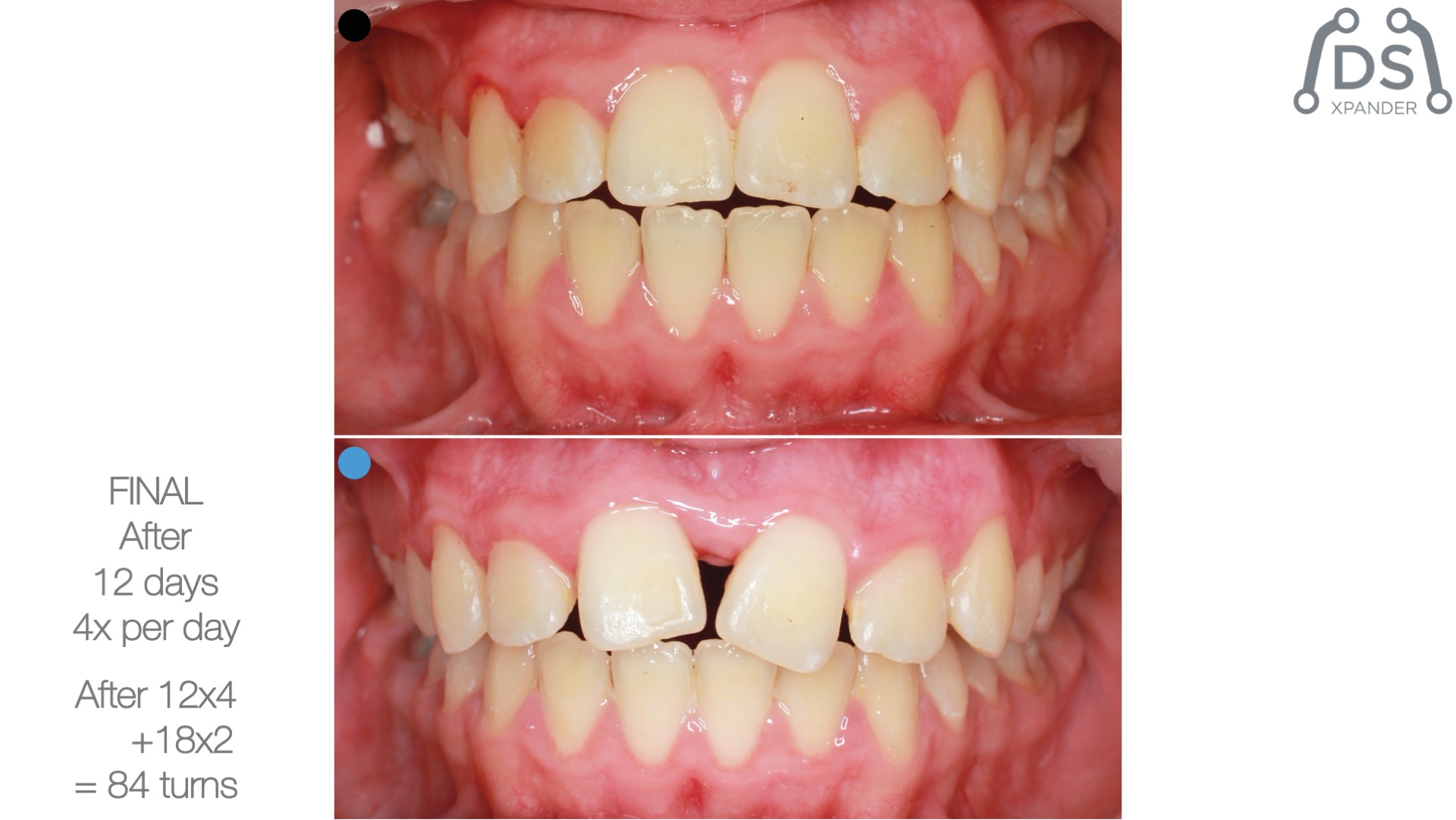
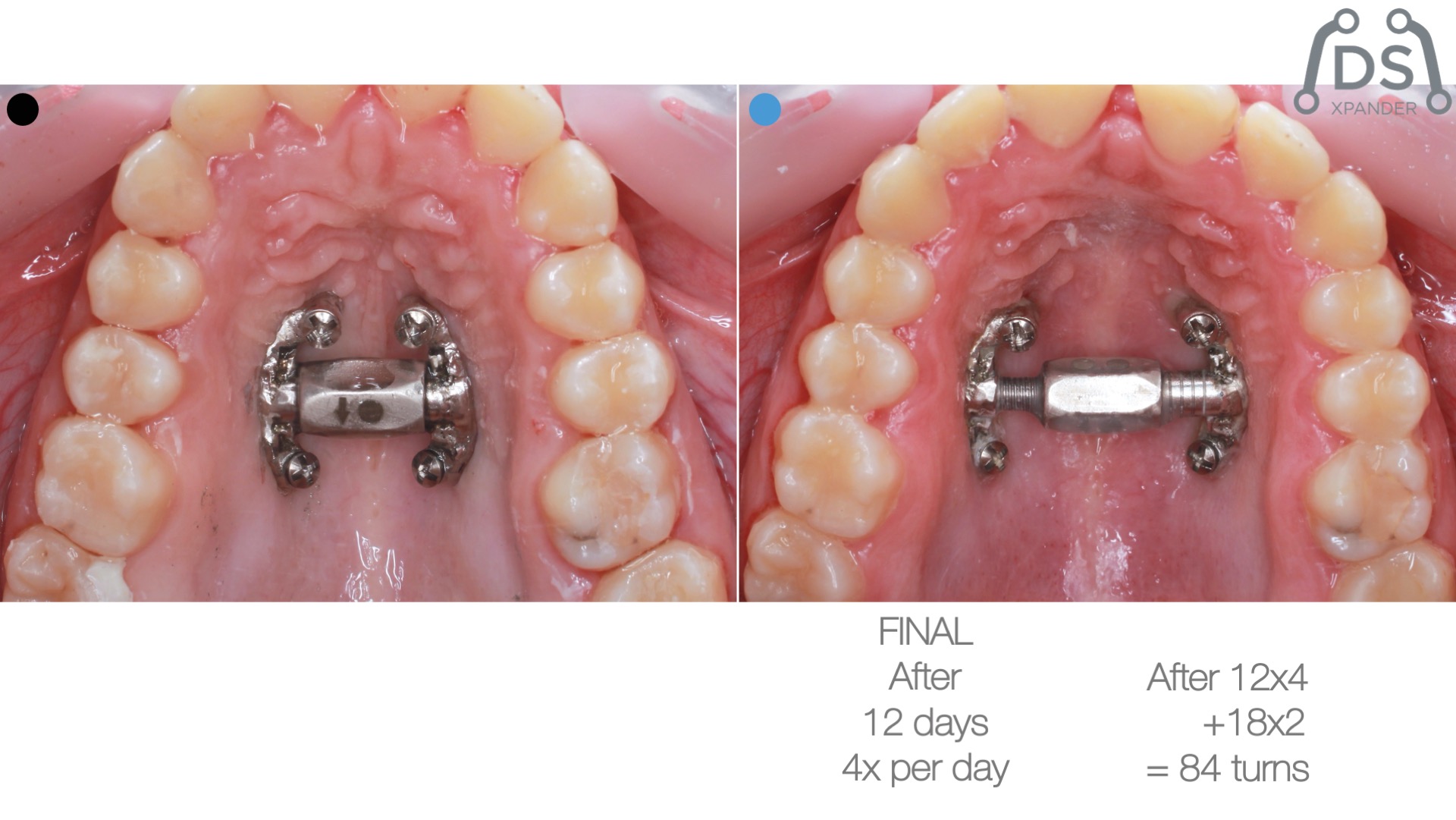
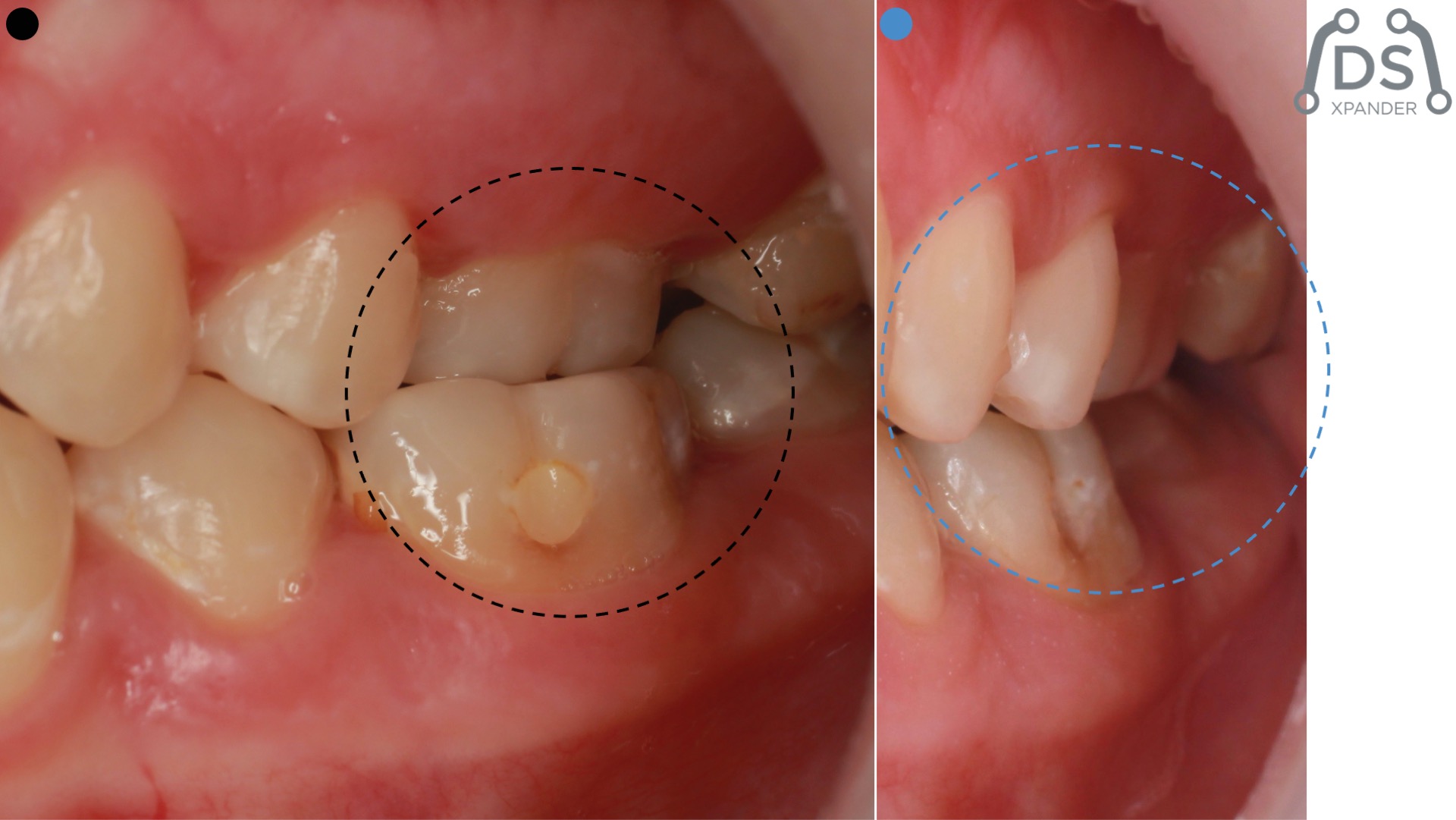
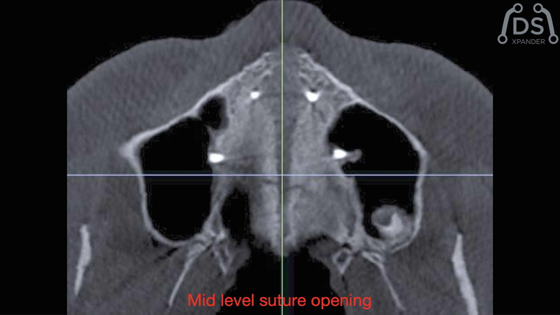
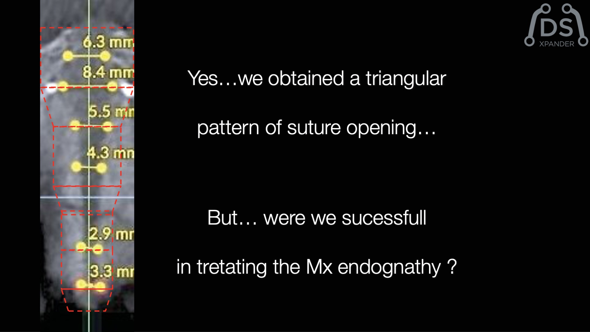
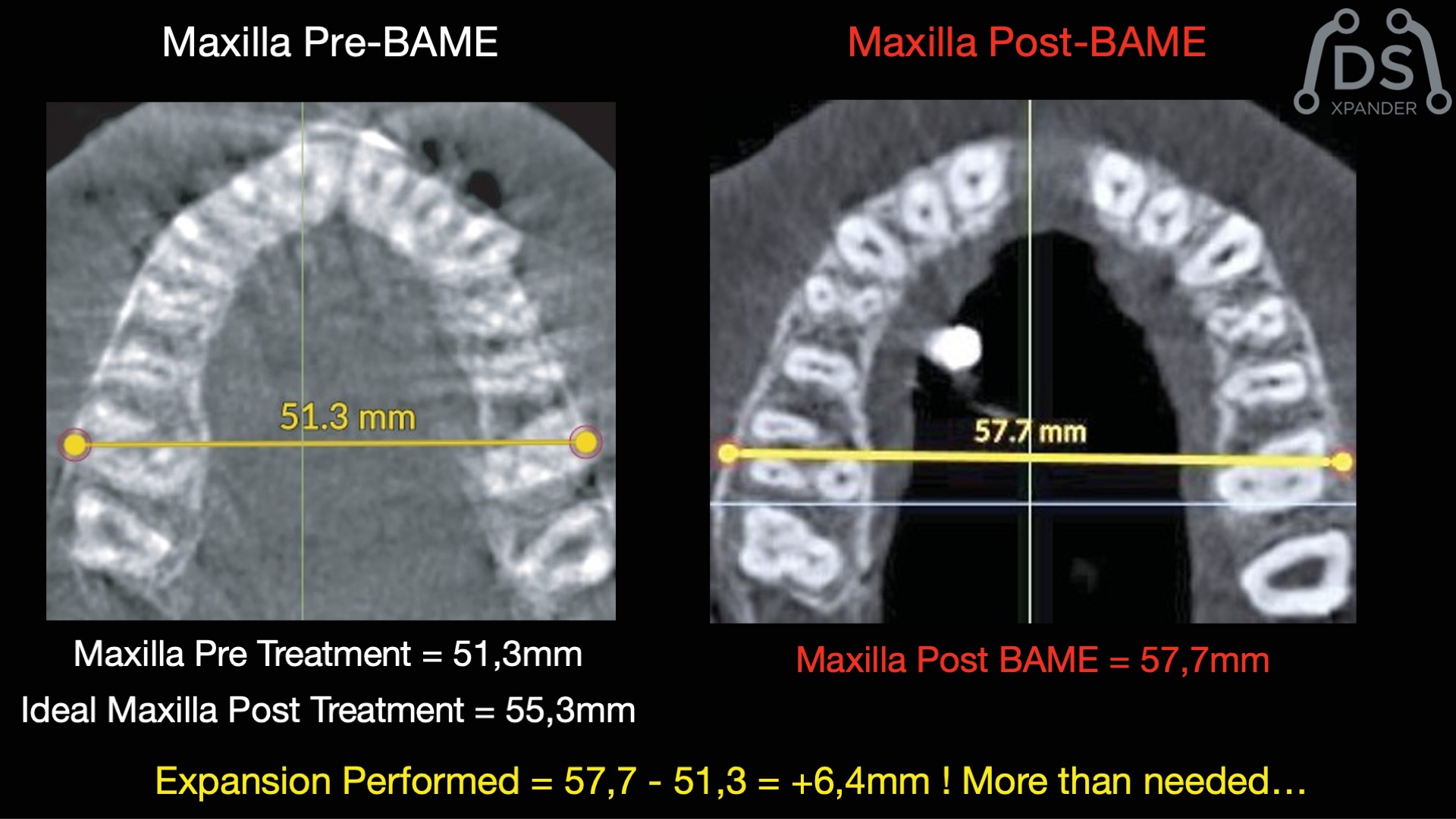
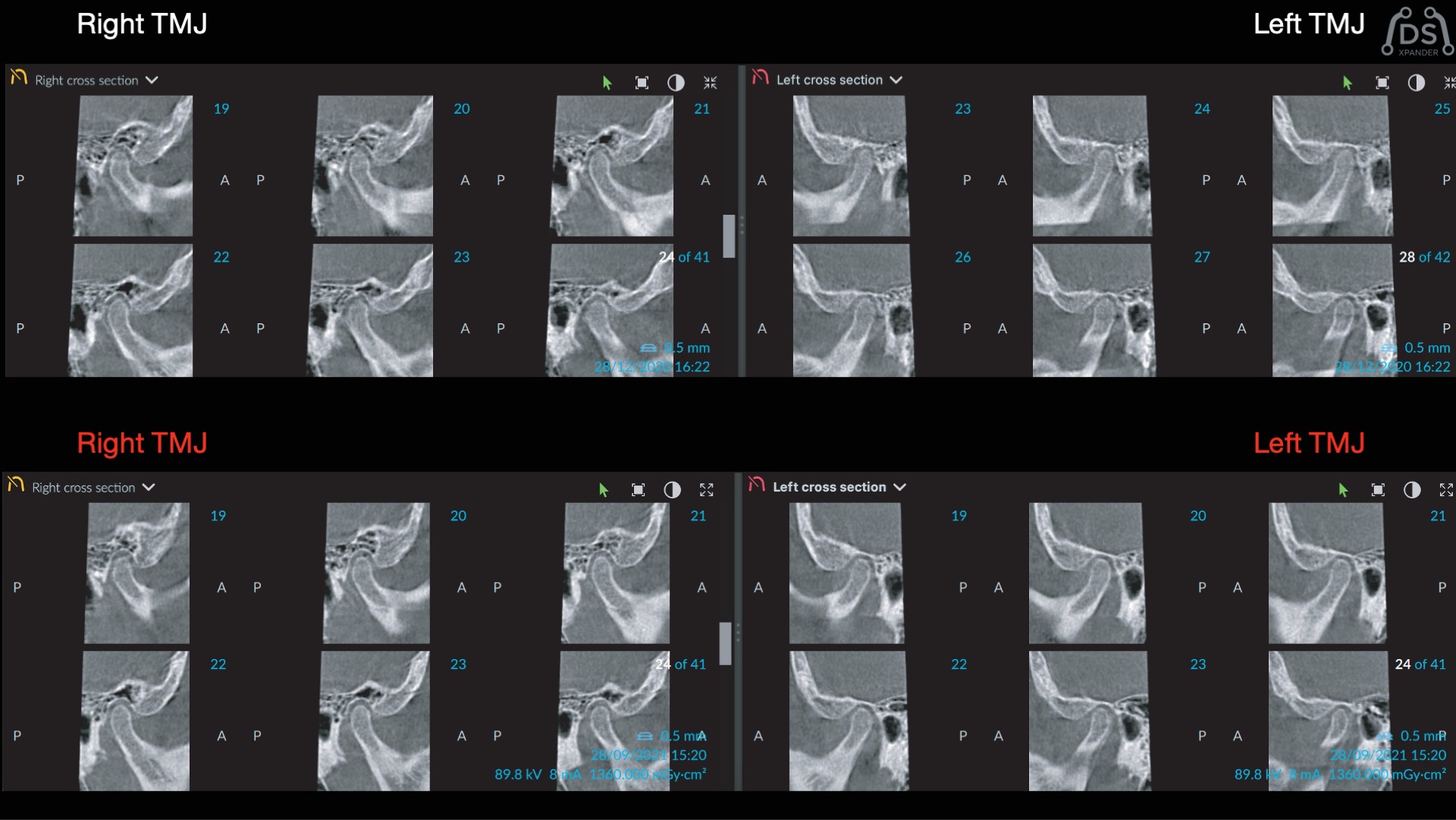
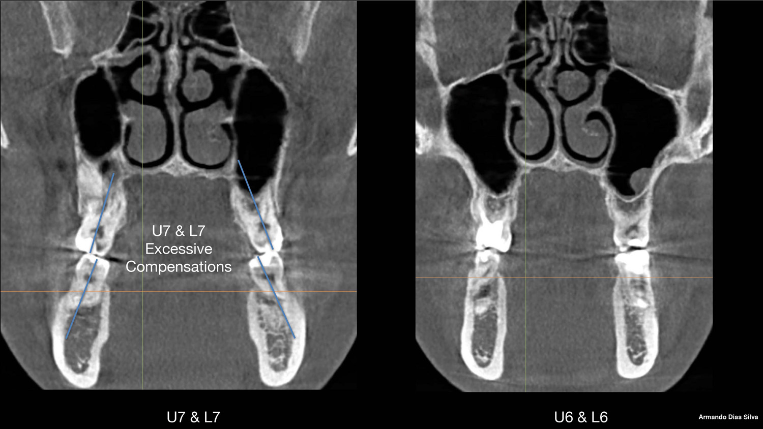
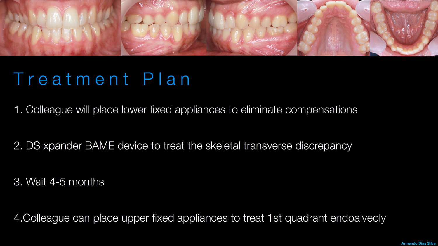
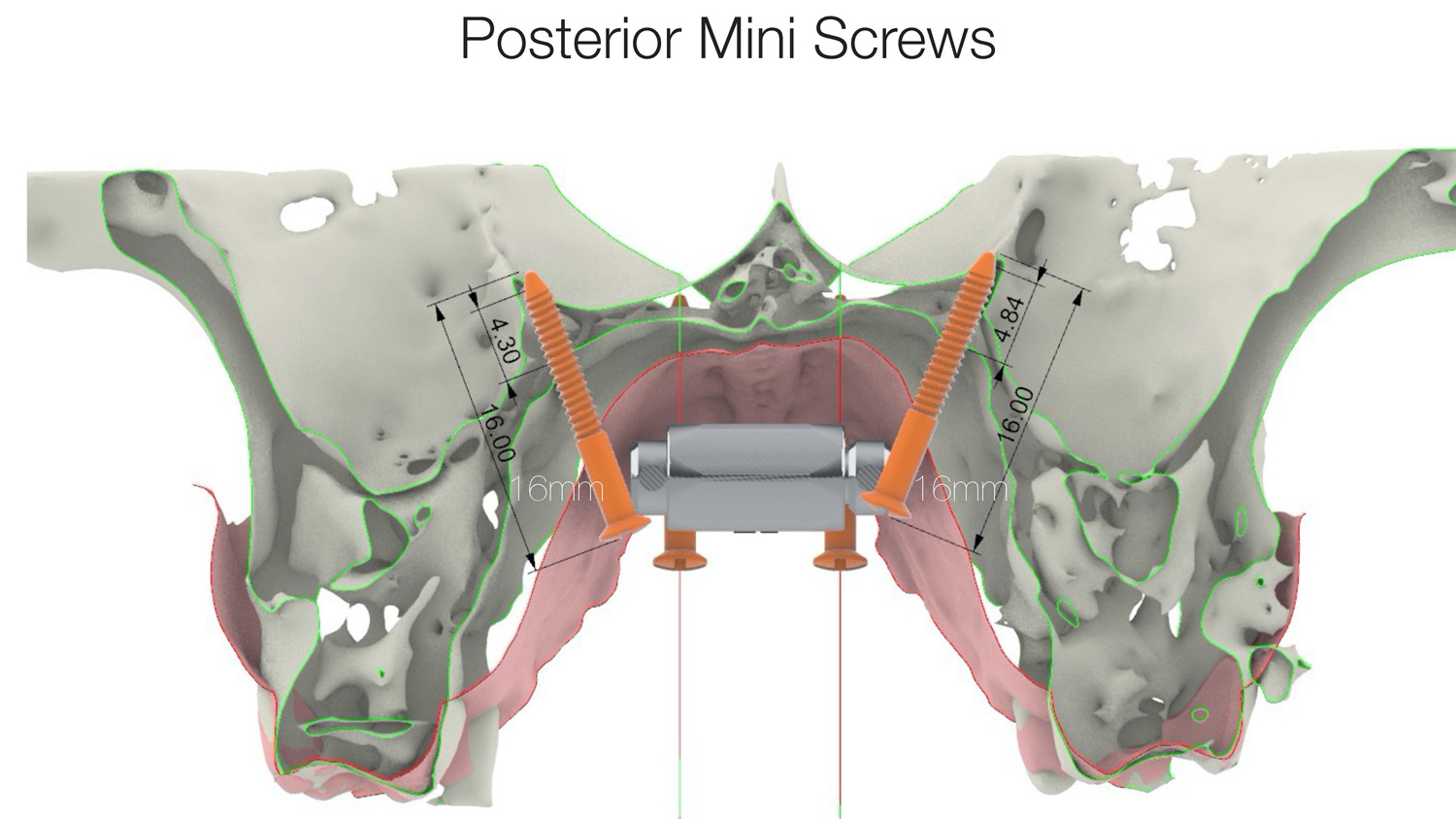
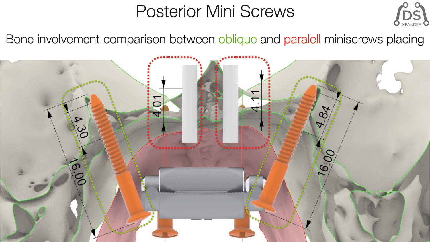
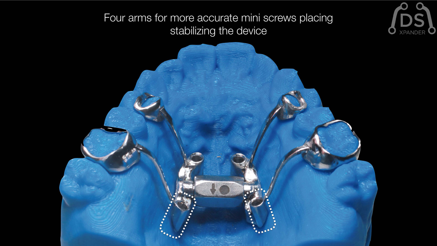
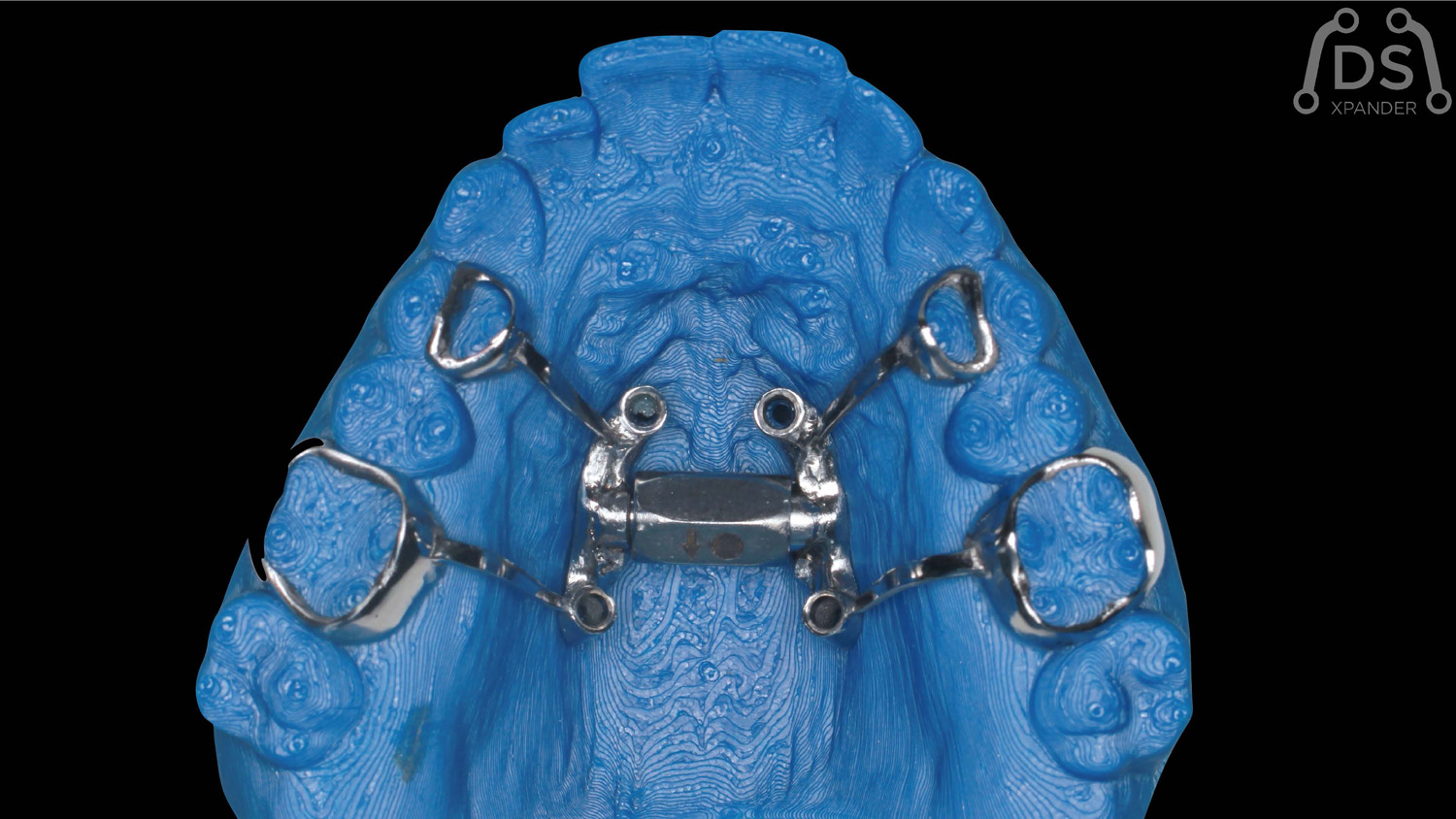
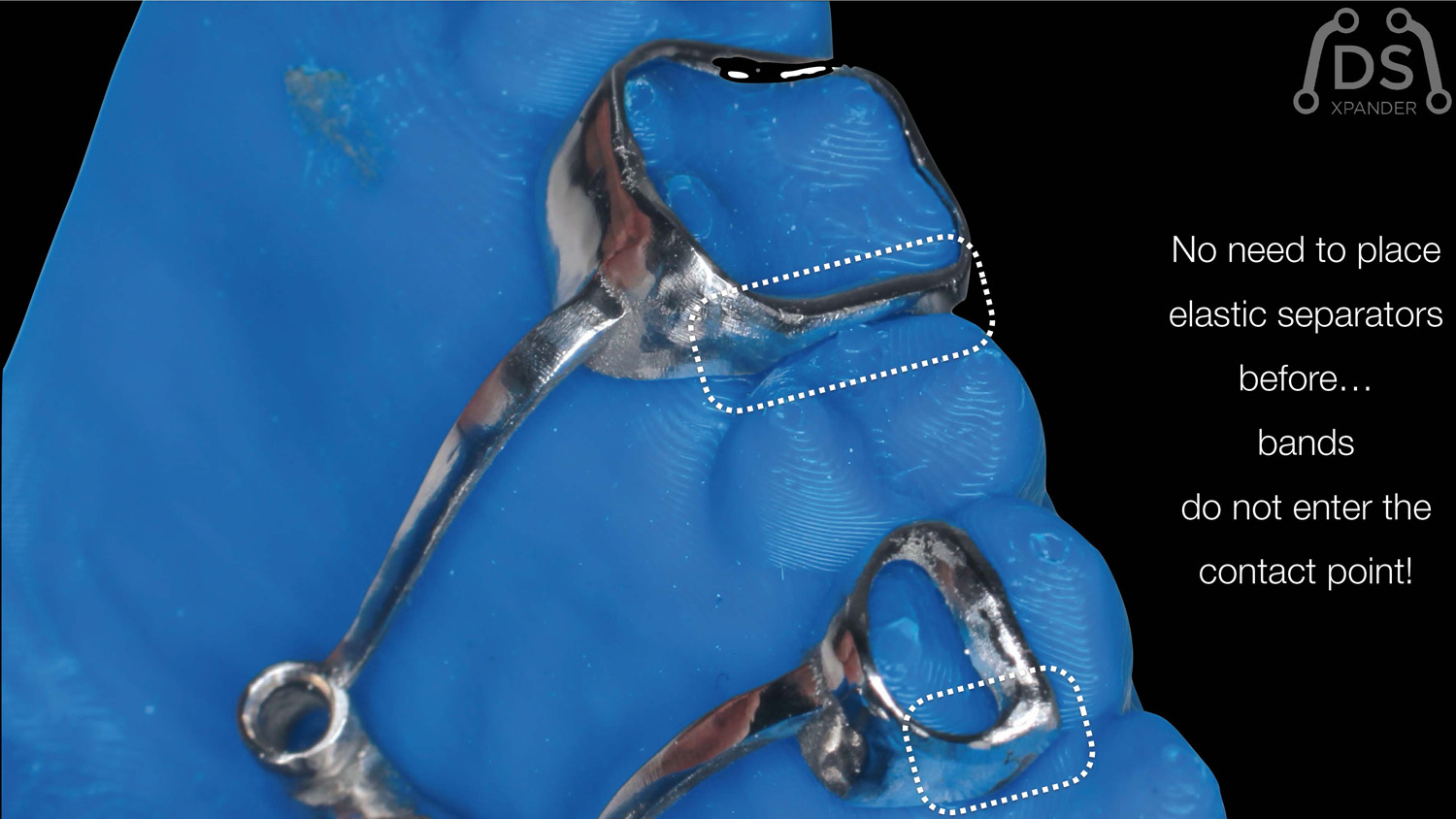
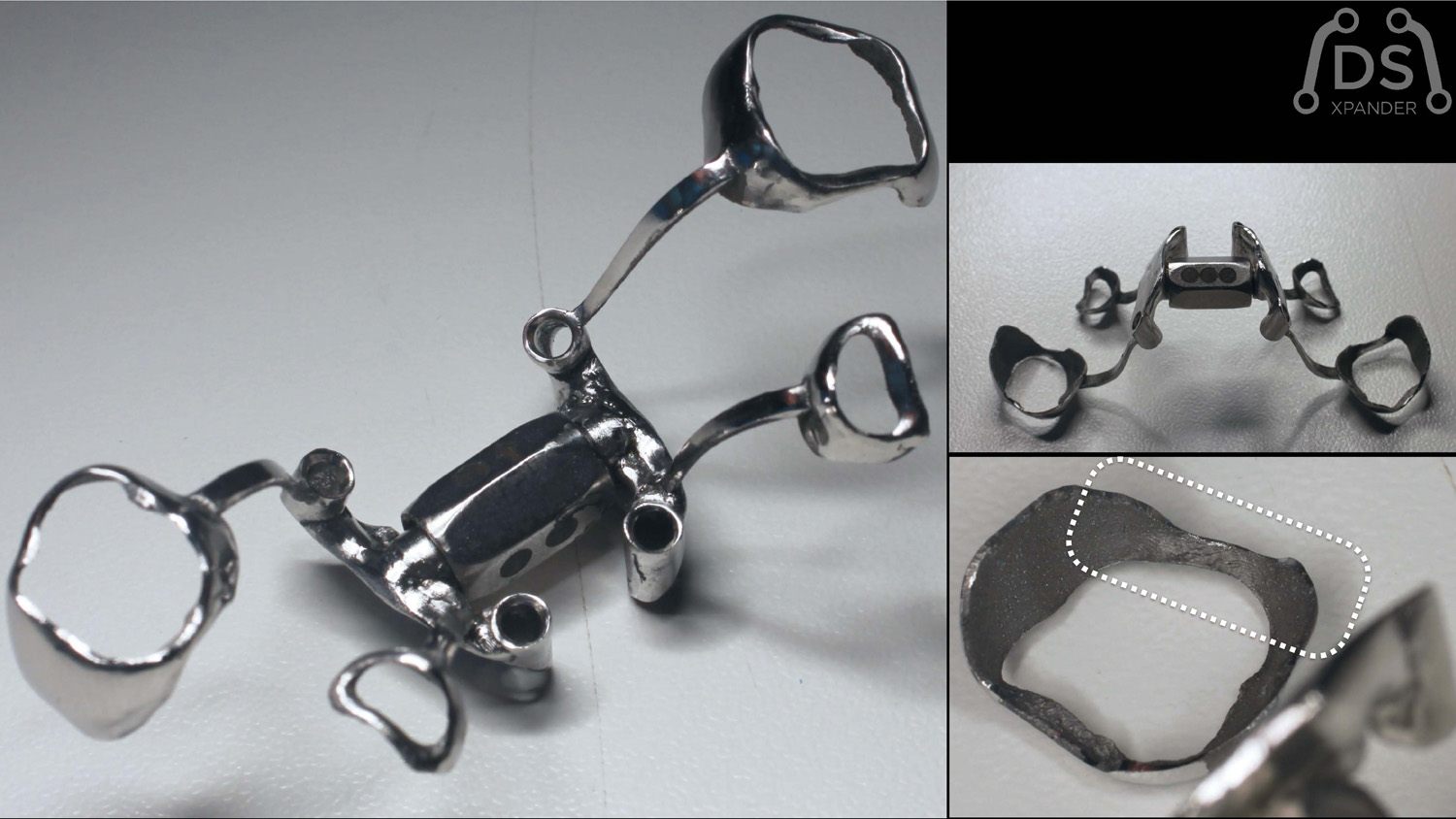
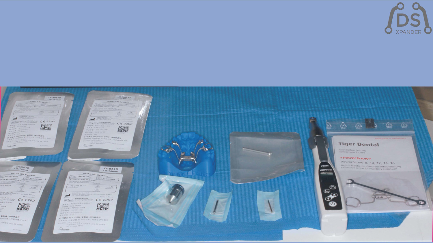
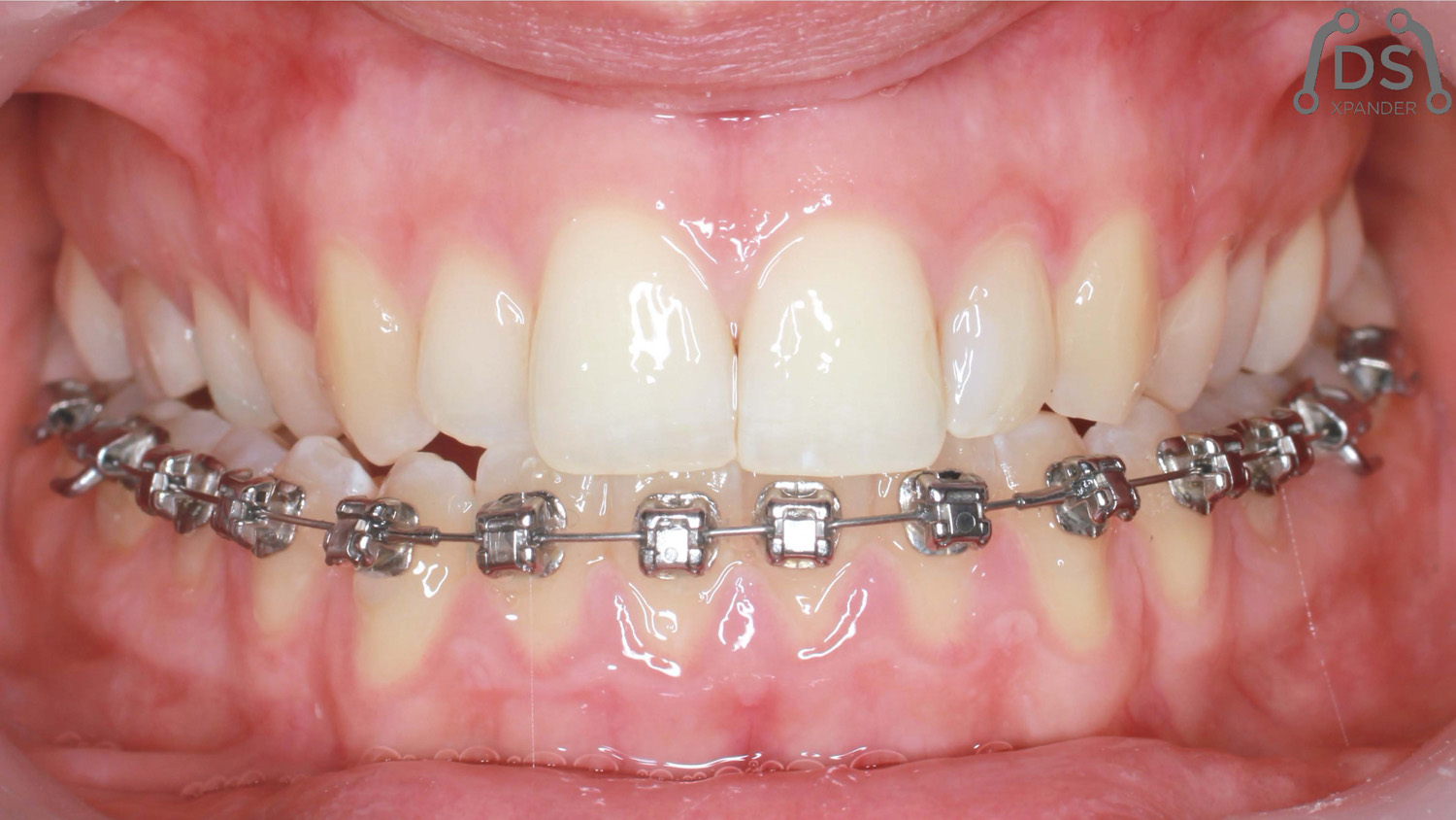
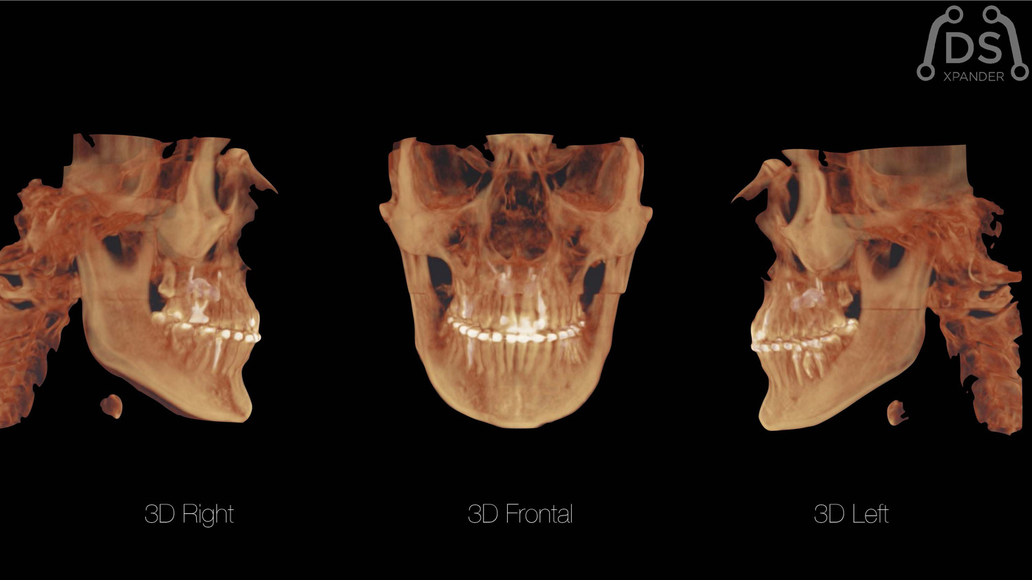
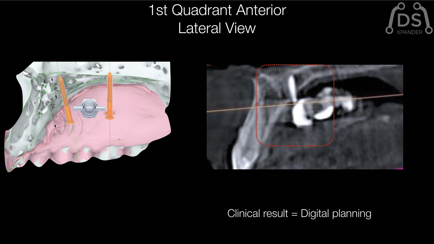
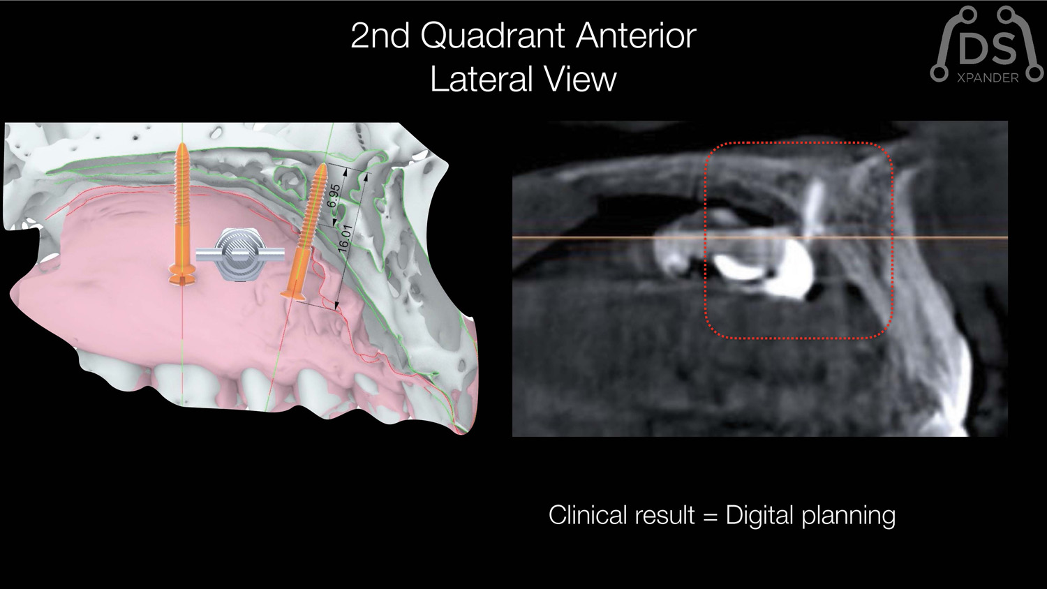
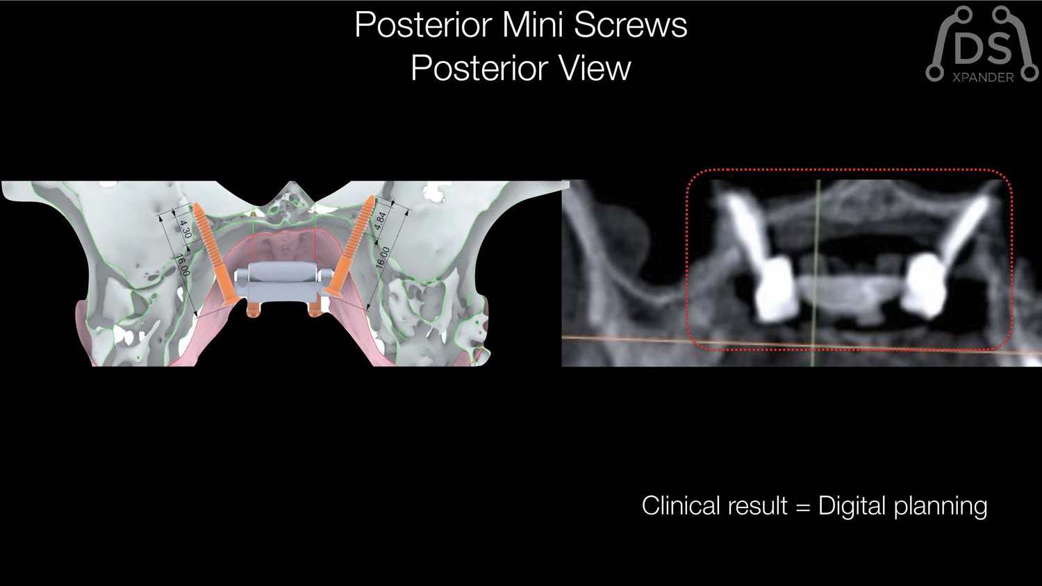
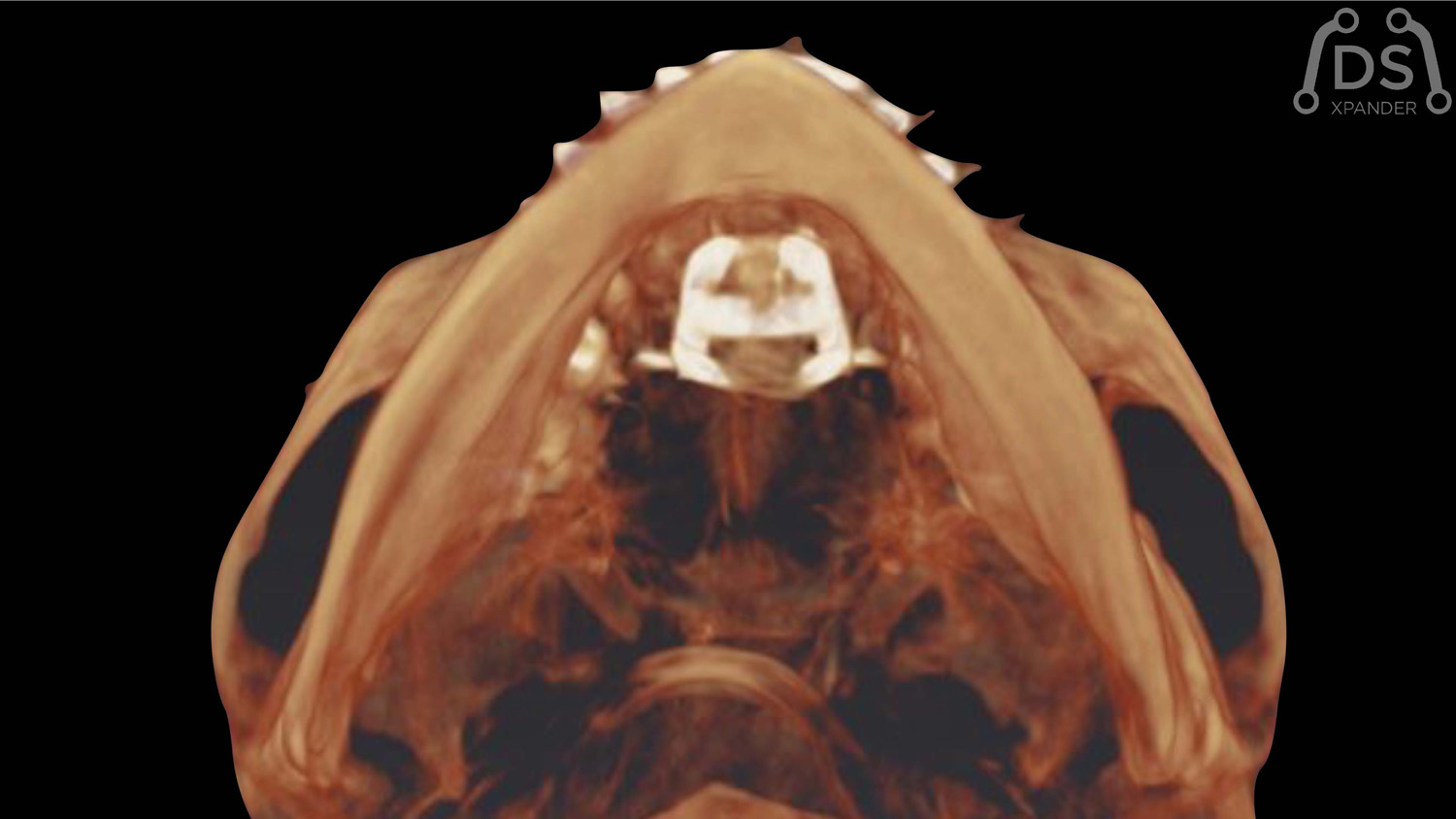
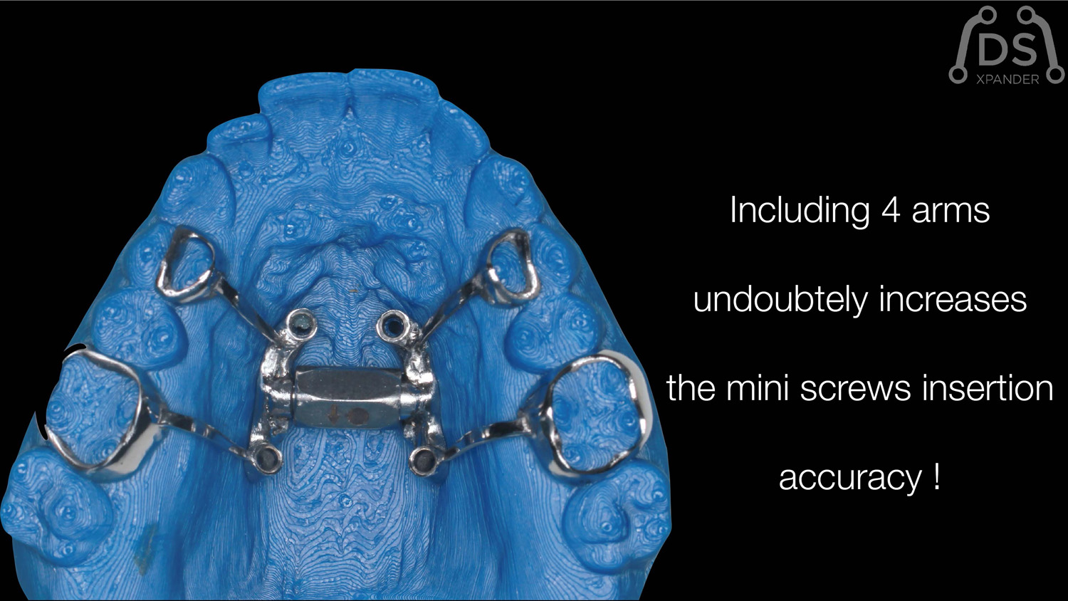
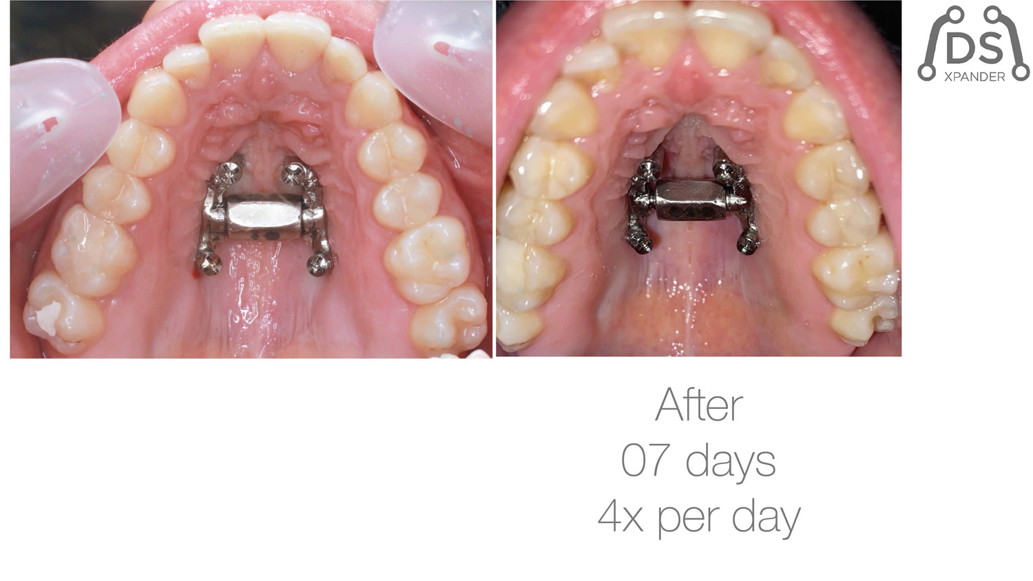
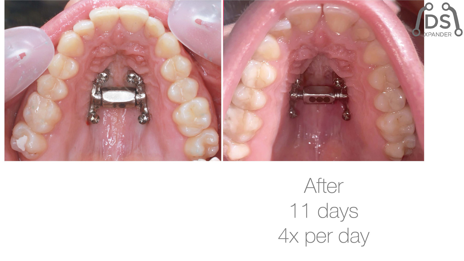
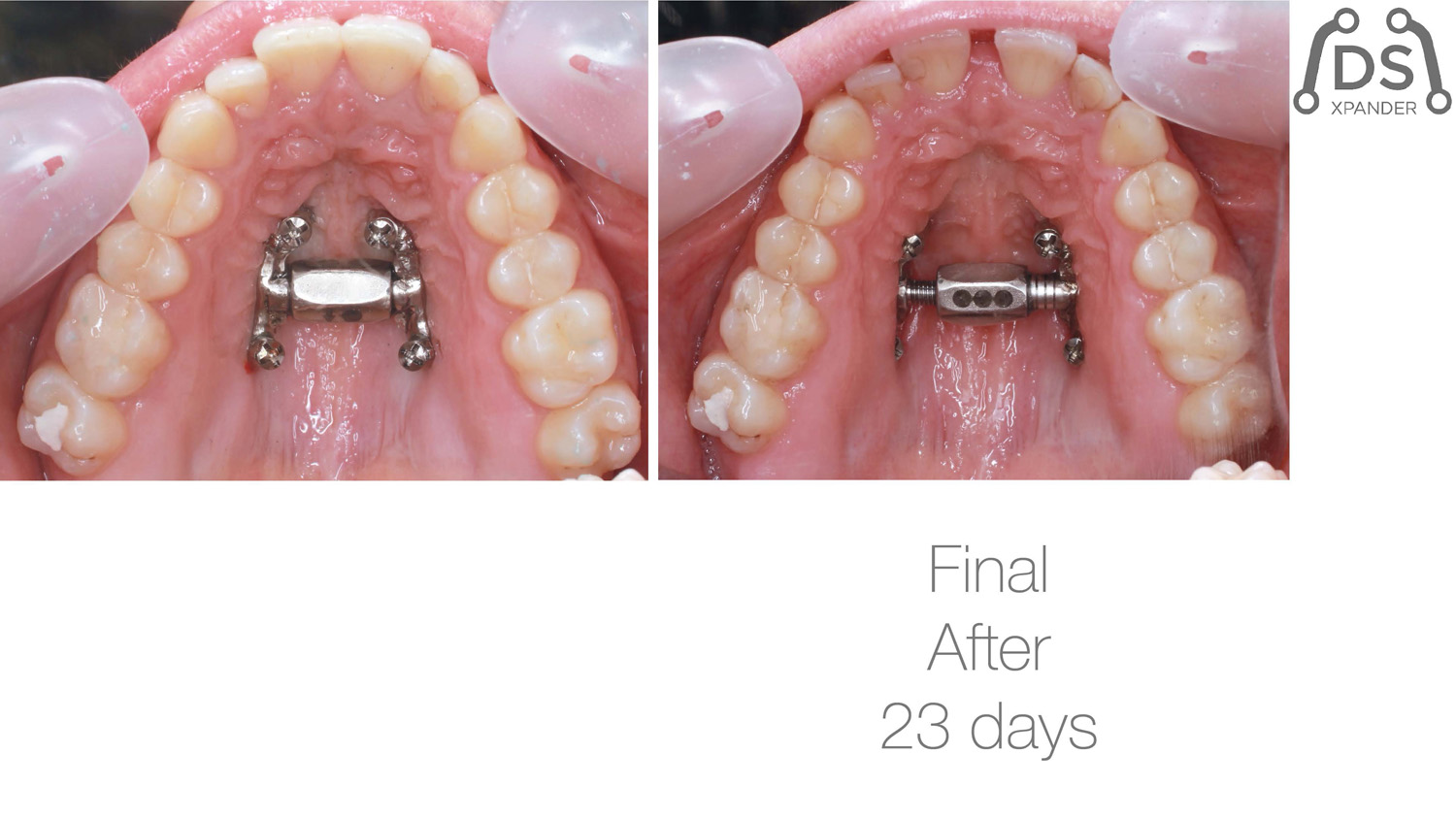
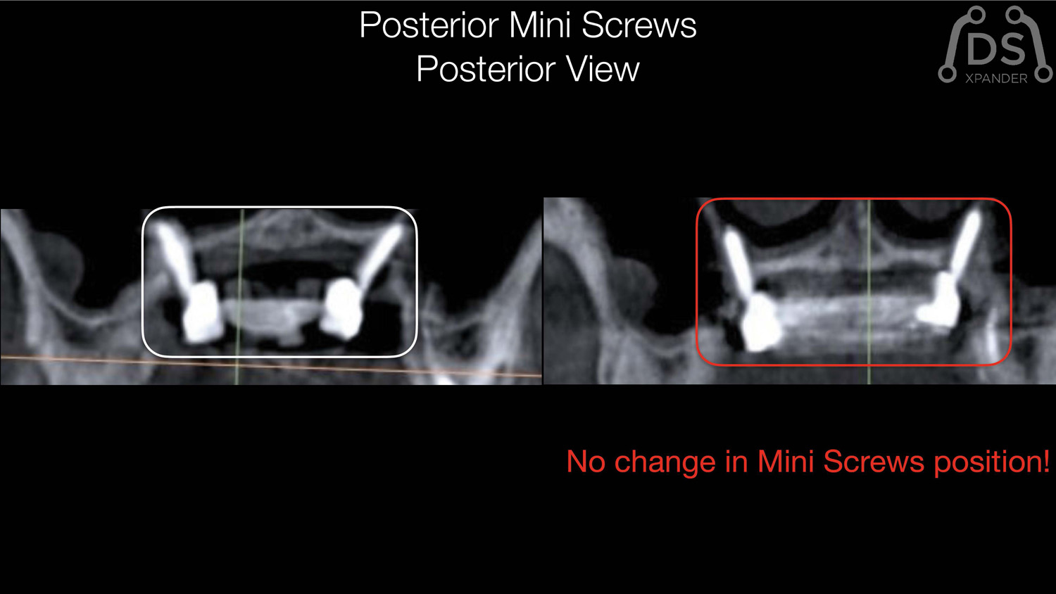
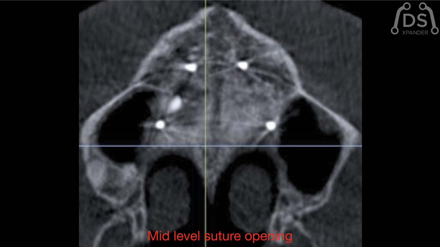
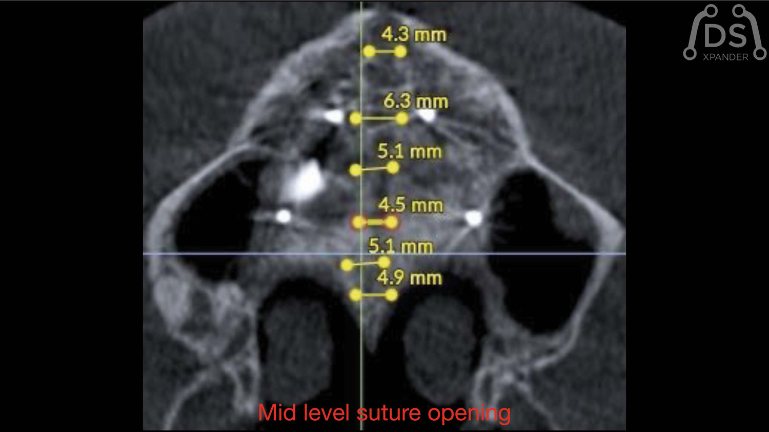
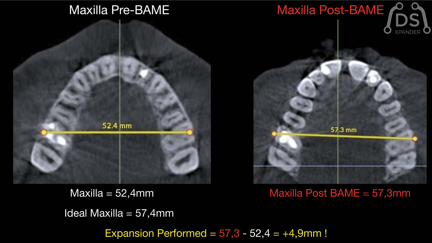
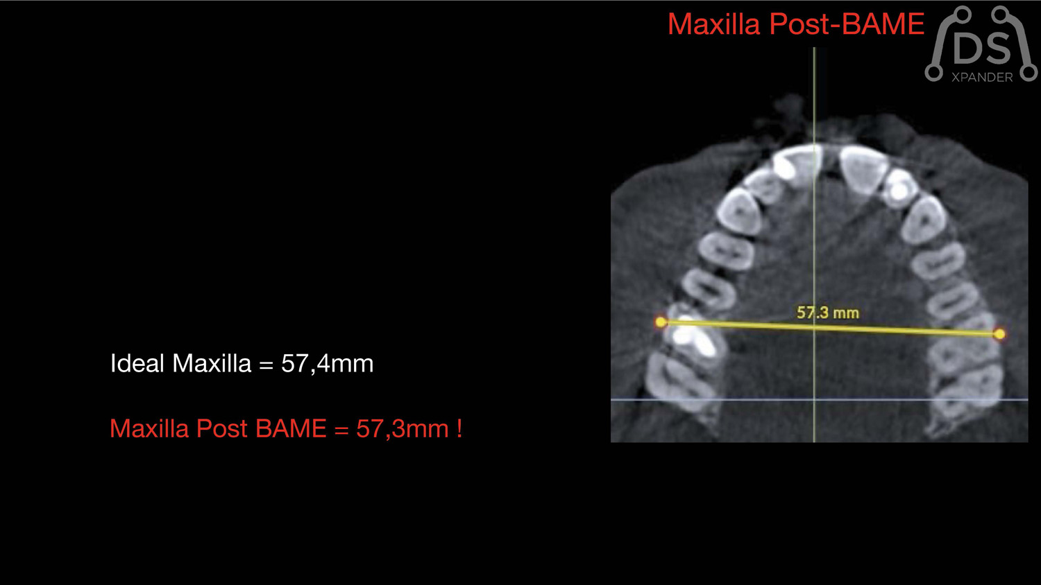
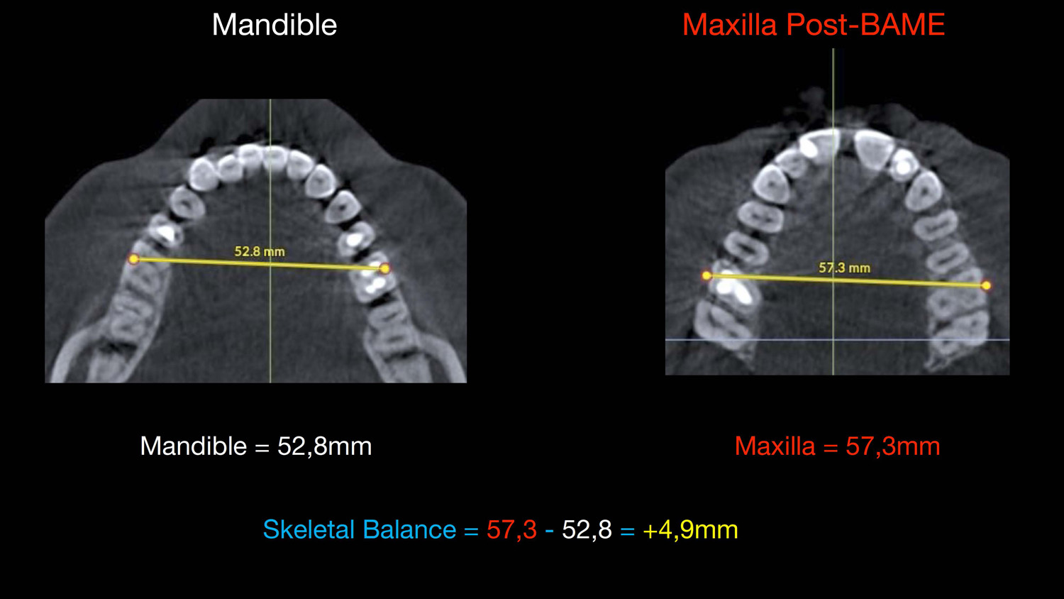
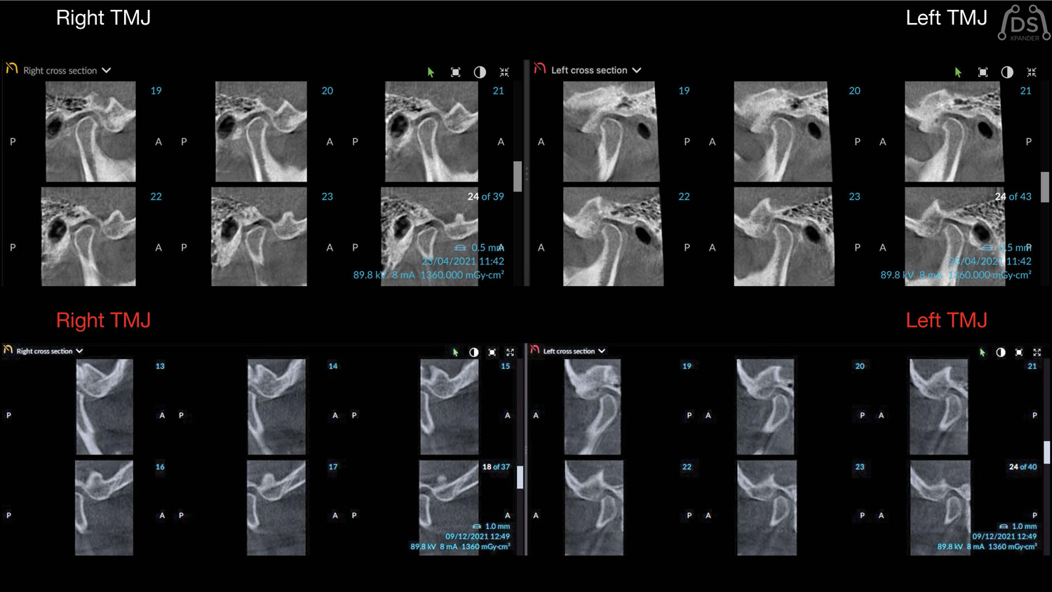
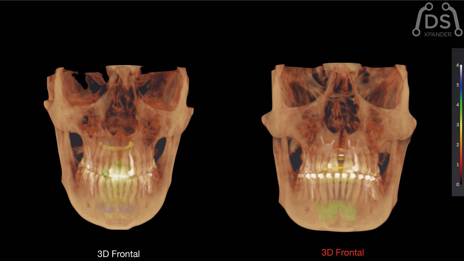
MARPE-BAME: Expansión palatina rápida.
Dr. Armando Dias da Silva
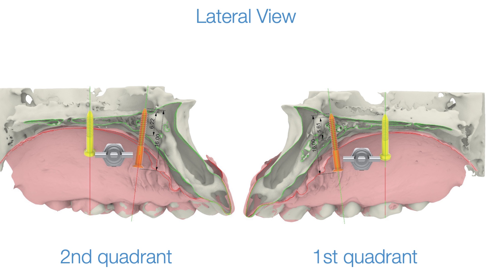
Planificación 3D con imágenes DICOM de CBCT para Expansión BAME con tornillos de fijación no paralelos.


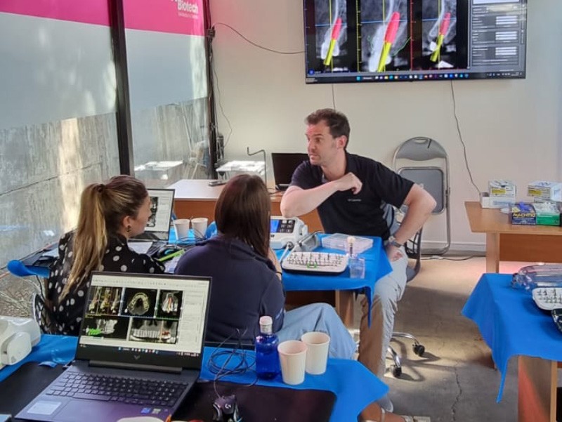
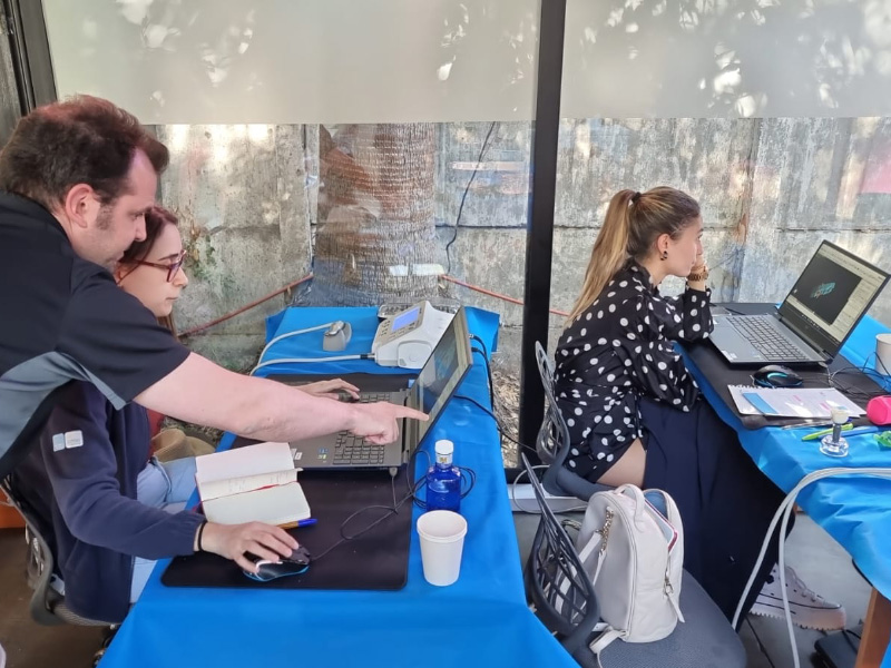
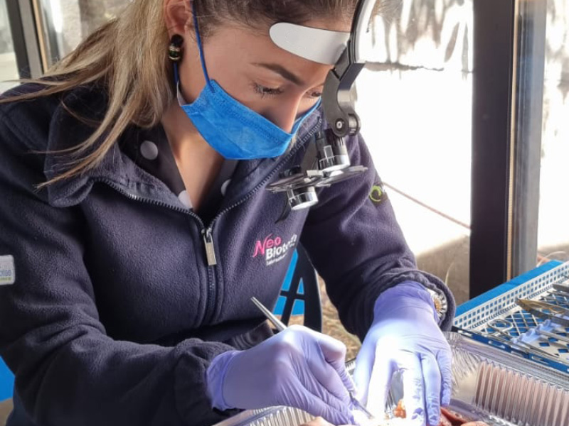
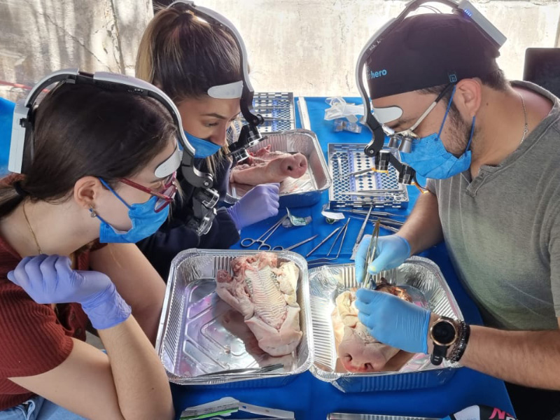
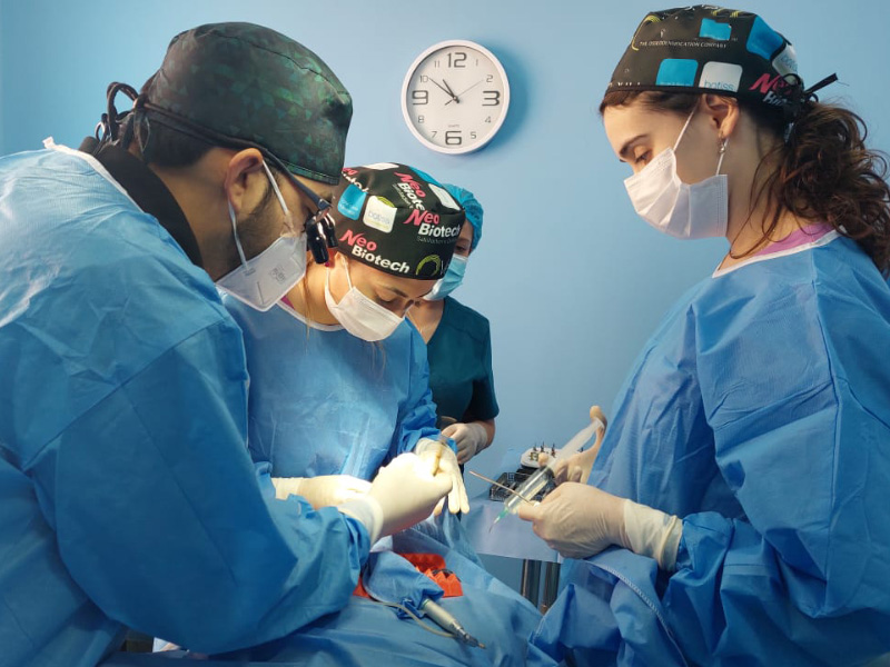
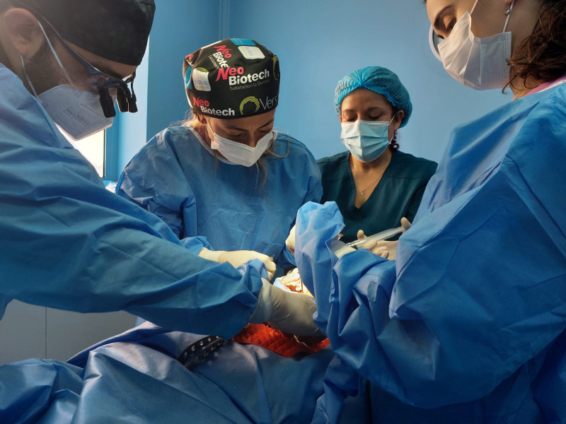
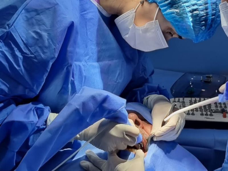
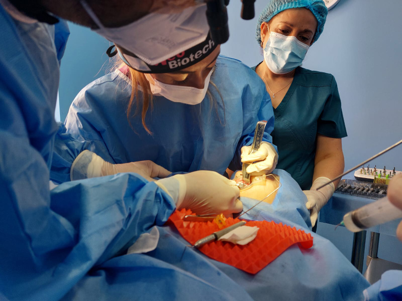
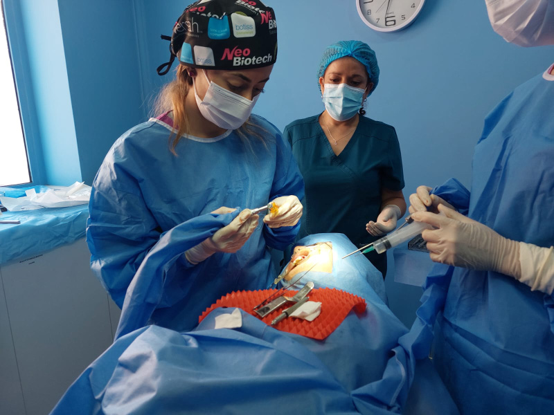
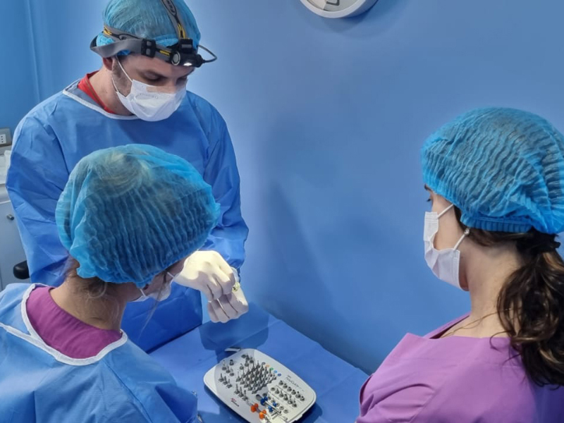
Cursos de Implanto-prótesis en Chile.
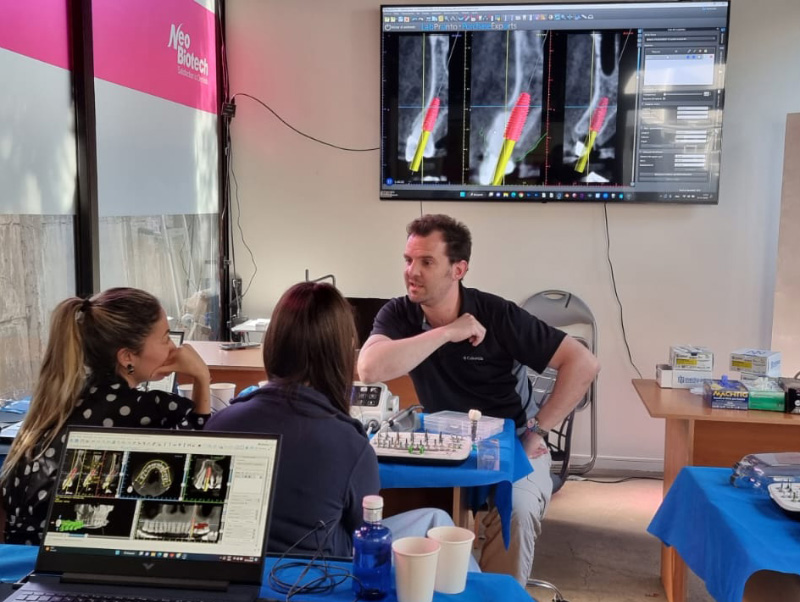
Próximo curso
4 al 9 de Diciembre de 2023
Cursos personalizados con ponentes internacionales
Implanto-prótesis y mucogingival
Dr. Luis Ignacio de Bellas Tulle
Dr. Miguel Olivares
Dr. Pablo Urrutia
Dr. Sebastián Bravo
Dr. Edgar Cabrera
Duración del curso:
Una semana
Modalidad:
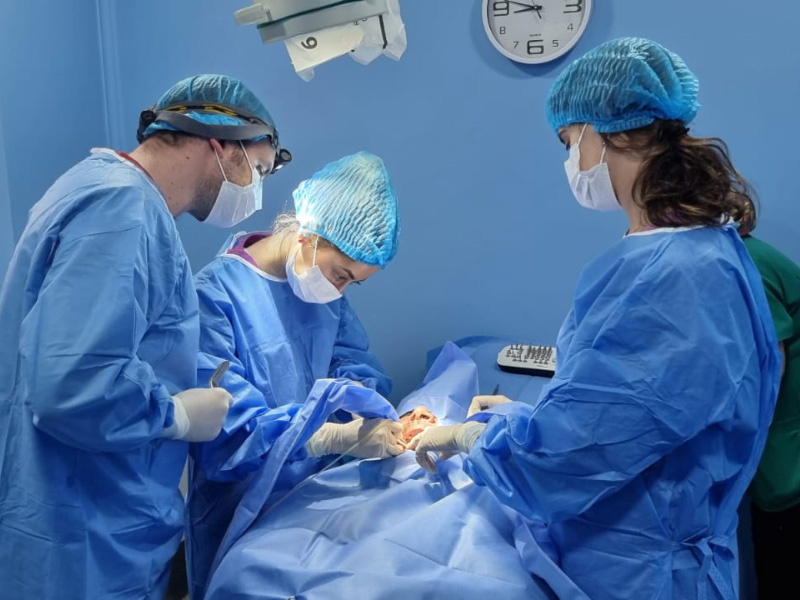
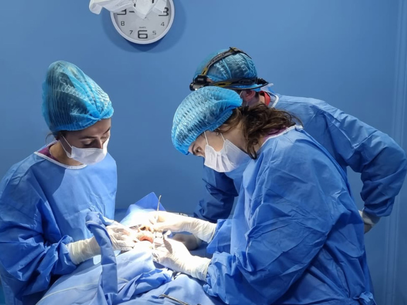
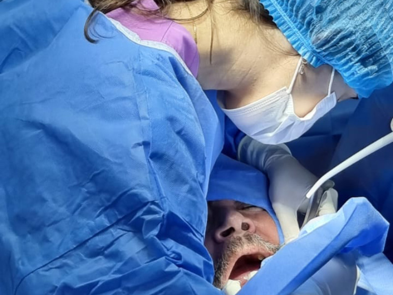
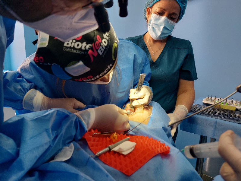
Teórico con Práctica de cirugías en pacientes reales
Cupo:
Limitado
Lugar:
Santiago de Chile
Consultas Teléfono 96.342.0478
Descripción y programa
Dirigido a Profesionales Odontólogos y Estomatólogos que deseen iniciarse o profundizar en sus conocimientos. Tres diferentes cursos.
Objetivos:
Iniciarse en la colocación quirúrgica de implantes oseointegrados con fines protésicos, comprendiendo la importancia del diagnóstico y la planificación como bases fundamentales del éxito estético y funcional a largo plazo. Obtener los conocimientos necesarios y habilidades prácticas para un diagnóstico y plan de tratamiento acorde a las necesidades del paciente, en el que se incluyan los más recientes avances de técnica y tecnología. Desarrollar las habilidades clínicas y quirúrgicas para la realización de tratamientos implantológicos según los estándares actuales. El curso es eminentemente práctico, la selección de pacientes se realiza en conjunto, al igual que la planificación y diagnóstico previo con supervisión en todo momento.
CURSO I
RESIDENCIA CLÍNICA EN IMPLANTOLOGÍA ORAL BÁSICA
Si te quieres introducir en la cirugía y empezar a colocar implantes sencillos te sugerimos apuntarte en este curso.
Qué harás en este curso:
-Principios básicos, oseointegración, fisiología, anatomía, calidad y disponibilidad ósea.
-Diseño y biomecánica de implantes.
-Diagnóstico, evaluación de Rayos-X y 3D.
-Práctica de tipos de incisiones, colgajos y suturas. Integración quirúrgica y protésica.
-Protocolo de fresado, colocación de implantes sencillos.
-Cirugía estética con enfoque en implantes dentales.
-Protocolos de tiempo y carga.
-Técnicas de impresión analógica y digital.
-Selección de material de rehabilitación, sector anterior y sector posterior.
Y mucho más…
CURSO II
RESIDENCIA CLÍNICA EN IMPLANTOLOGÍA ORAL AVANZADA
Este nivel es el tuyo si ya conoces técnicas implantológicas, tu experiencia quirúrgica definirá tus límites de acuerdo con tu habilidad quirúrgica. Resolverás casos más complejos que te darán destreza en situaciones más difíciles.
Qué harás en este curso:
-Colocación de implantes con o sin biomateriales.
-Implantes inmediatos post-extracción.
-Expansiones en crestas atróficas.
-Elevación de seno, reparación de Membrana de Schneider.
-ROGT avanzada, regeneraciones óseas severas
-Biomateriales, membranas, chinchetas, tornillos.
-Suturas: punto U, Donati, continua, a periostio, etc.
-Regularizaciones totales de arcada.
-Exposición de mentonianos.
-Extracción de cuerpos extraños en senos.
CURSO III
RESIDENCIA CLÍNICA EN CIRUGÍA MUCOGINGIVAL Y PERI-IMPLANTOLOGÍA AVANZADA
Este curso está destinado a médicos dentistas con práctica en implantología.
Qué harás en este curso:
-Macroanatomía gingival y diagnóstico periodontal.
-Sondeo periodontal – dientes vs implantes.
-Principios de cirugía periodontal.
-Peeling gingival.
-Tipos de incisiones y colgajos: importancia en Periodoncia.
-Técnicas de sutura periodontal.
-Elongación coronario: bisel externo vs bisel interno.
-Recuperación del espacio biológico.
-Cuña proximal: técnicas de Kramer, Robinson y Grein.
-Técnicas de cirugía periodontal y periimplantaria: Injerto gingival libre e injerto de tejido conjuntivo.
-Técnicas de cobertura radicular.
-Técnicas de aumento de encía queratinizada.
-Mejora de perfil de emergencia (sector anterior y posterior).
-Prevención de complicaciones estéticas periimplantarias.
-Aumento de reborde edéntulo con tejido gingival mixto.
-Evaluación de tejidos blandos para crear el perfil de emergencia correcto.
-Periimplantitis: causas, tratamiento quirúrgico y prevención.
-Cirugía en pacientes
-Tres cirugías por día, por alumno.
Fotos de curso personalizado


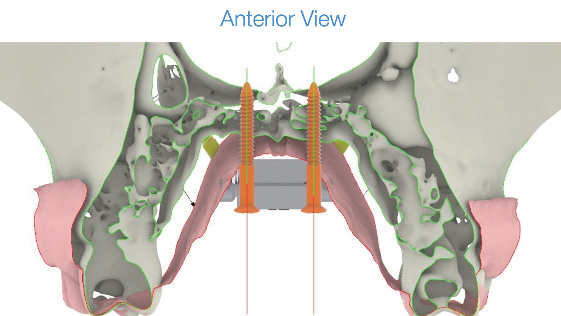
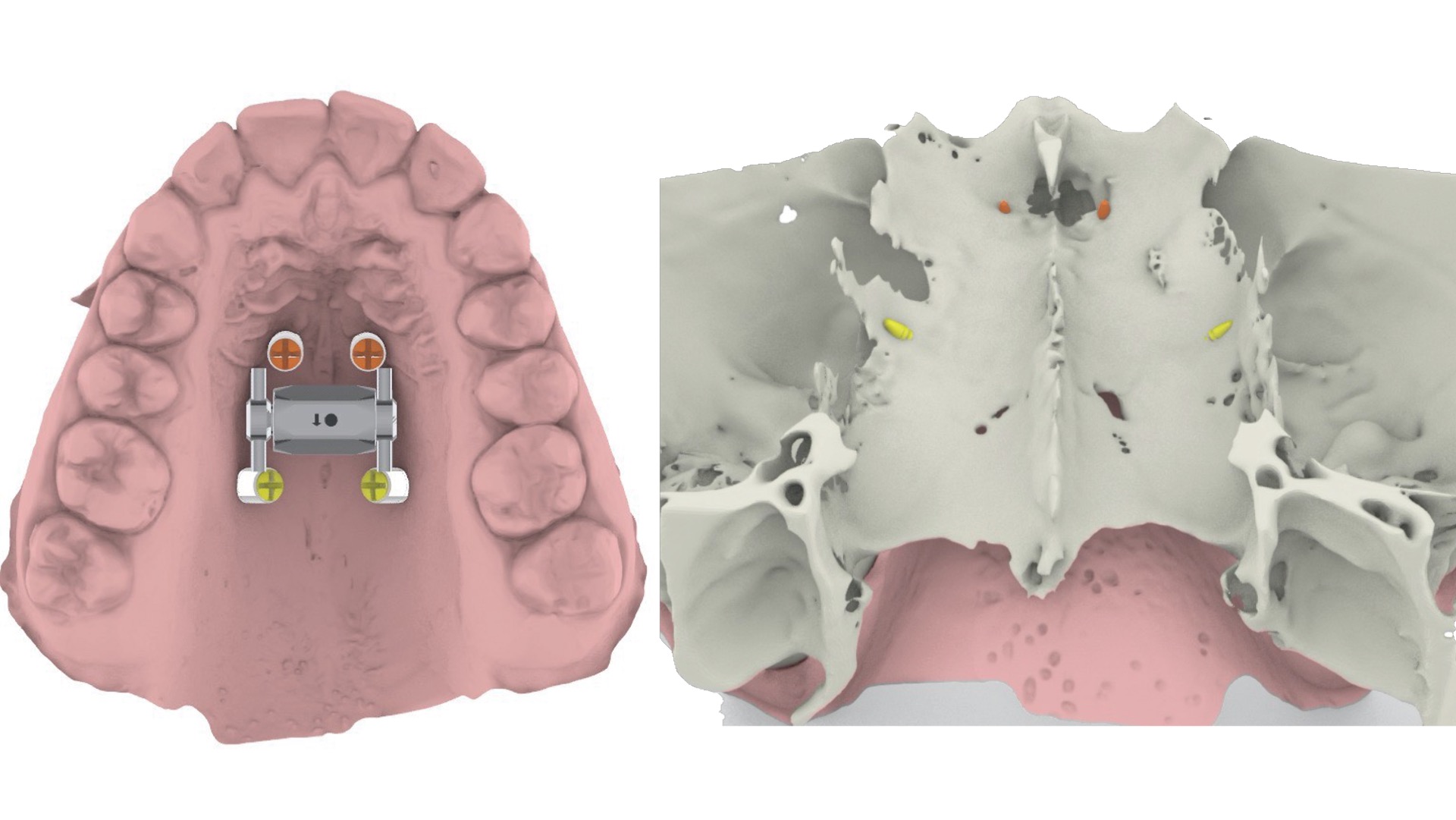
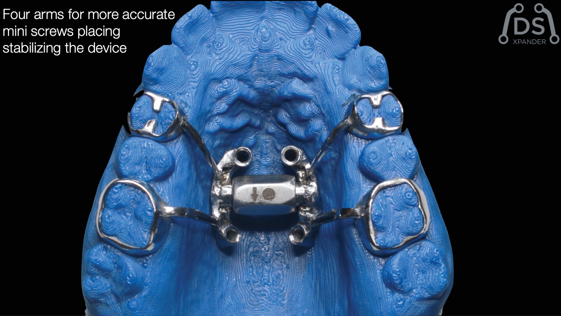
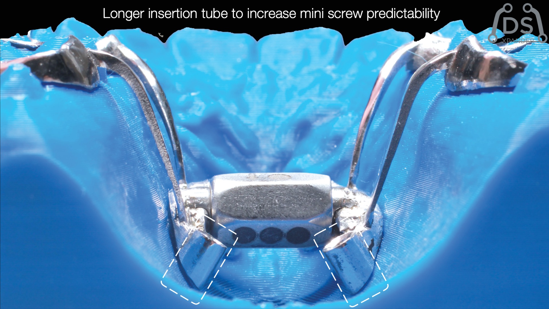
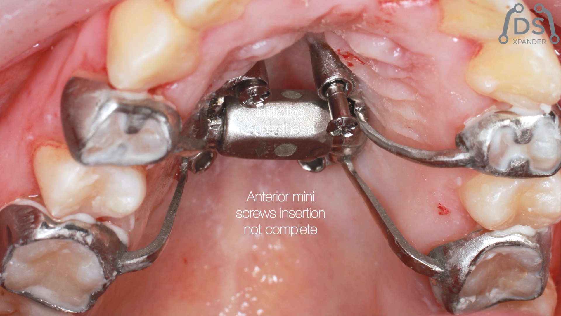
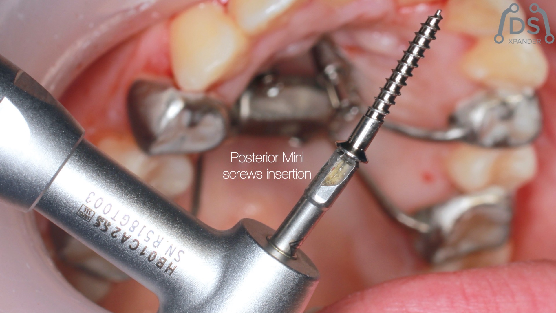
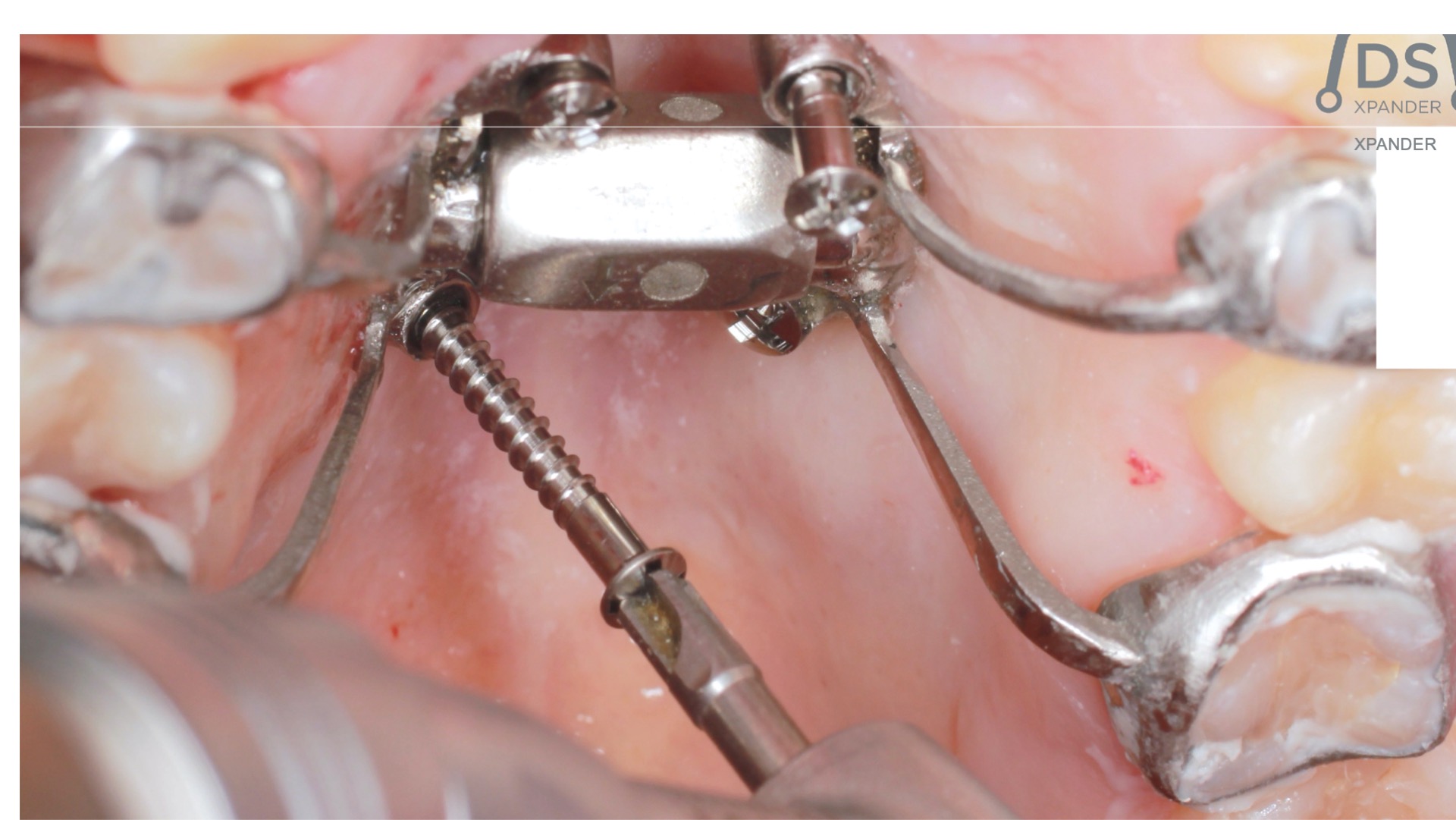
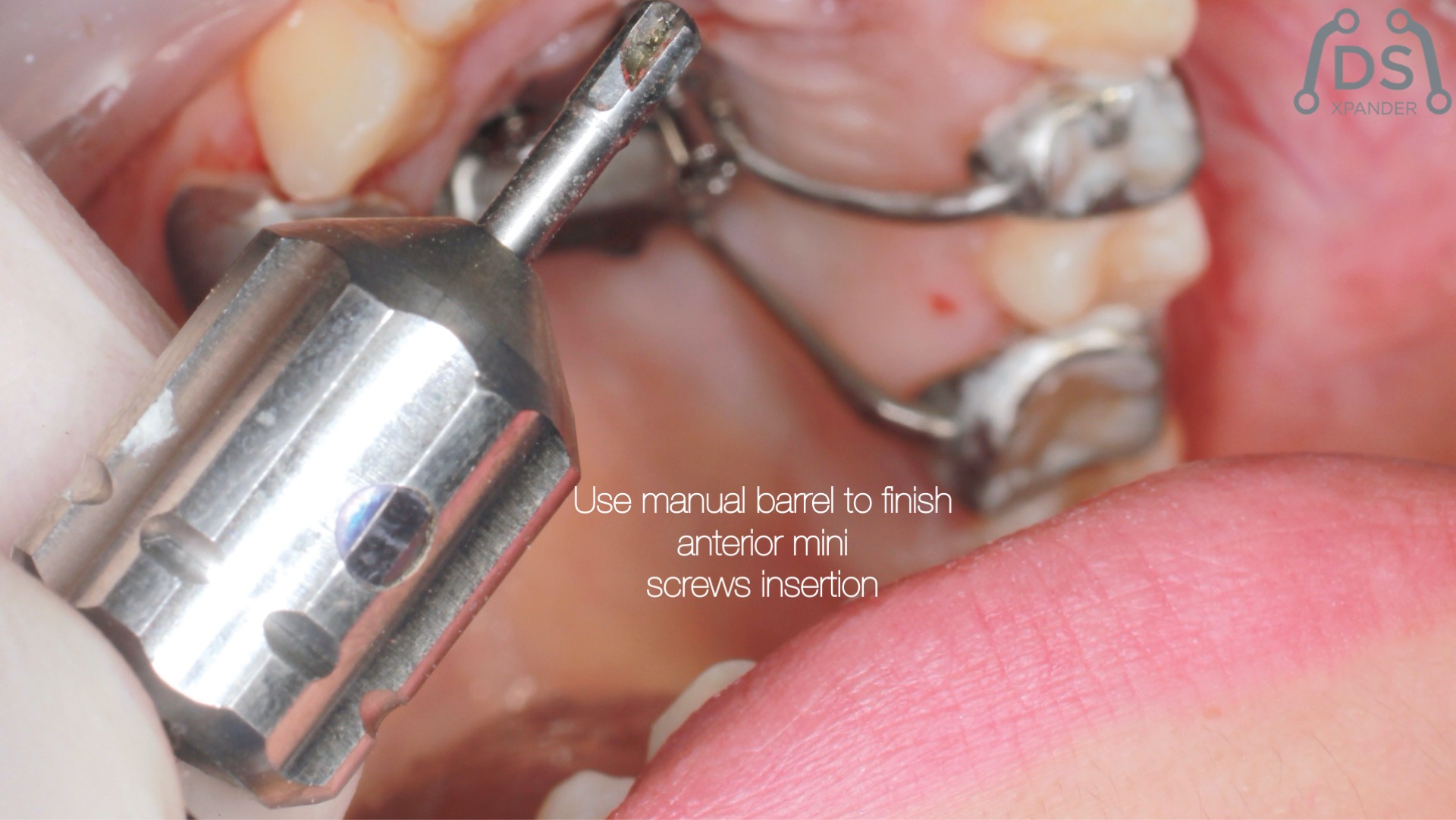
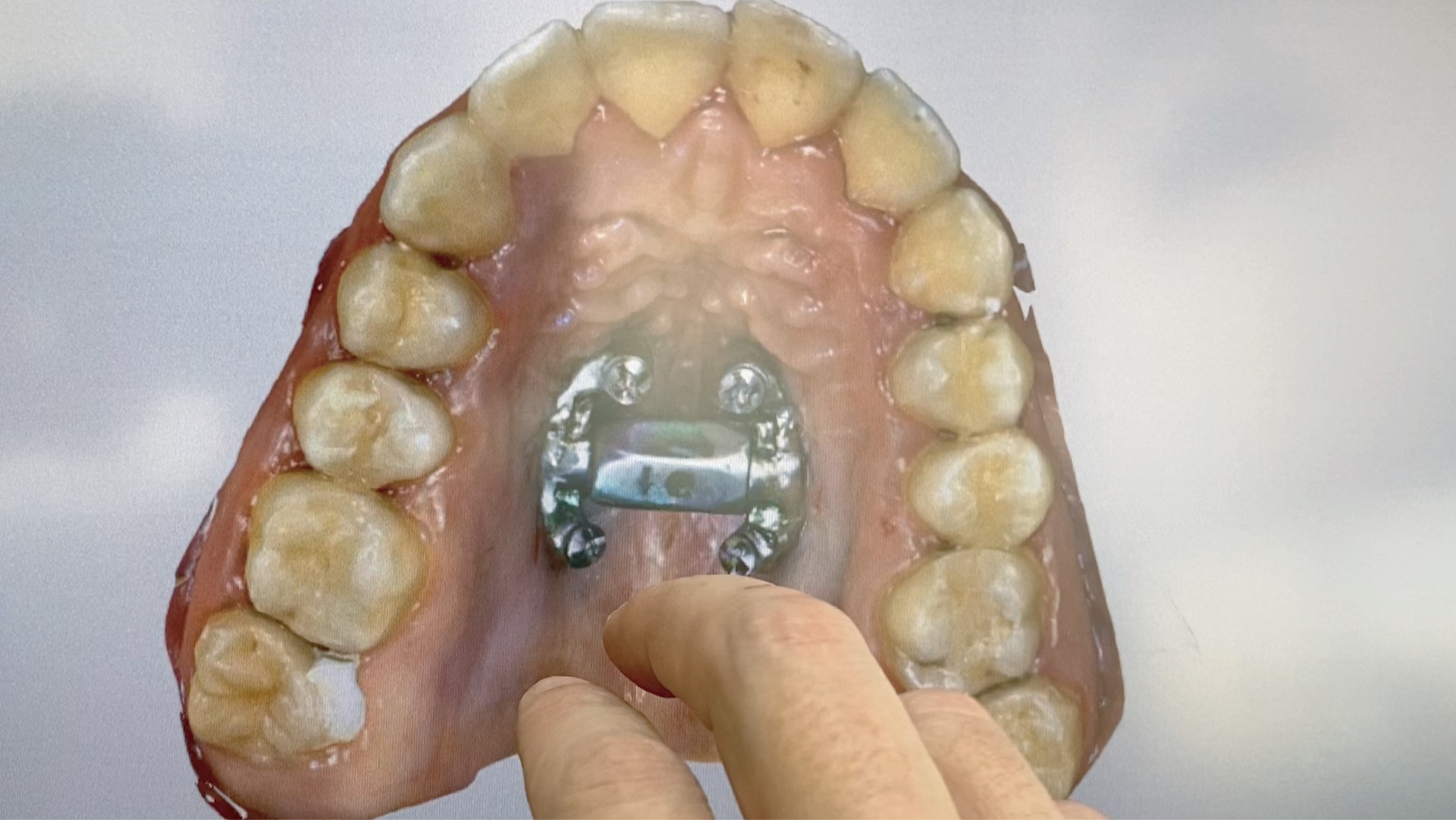
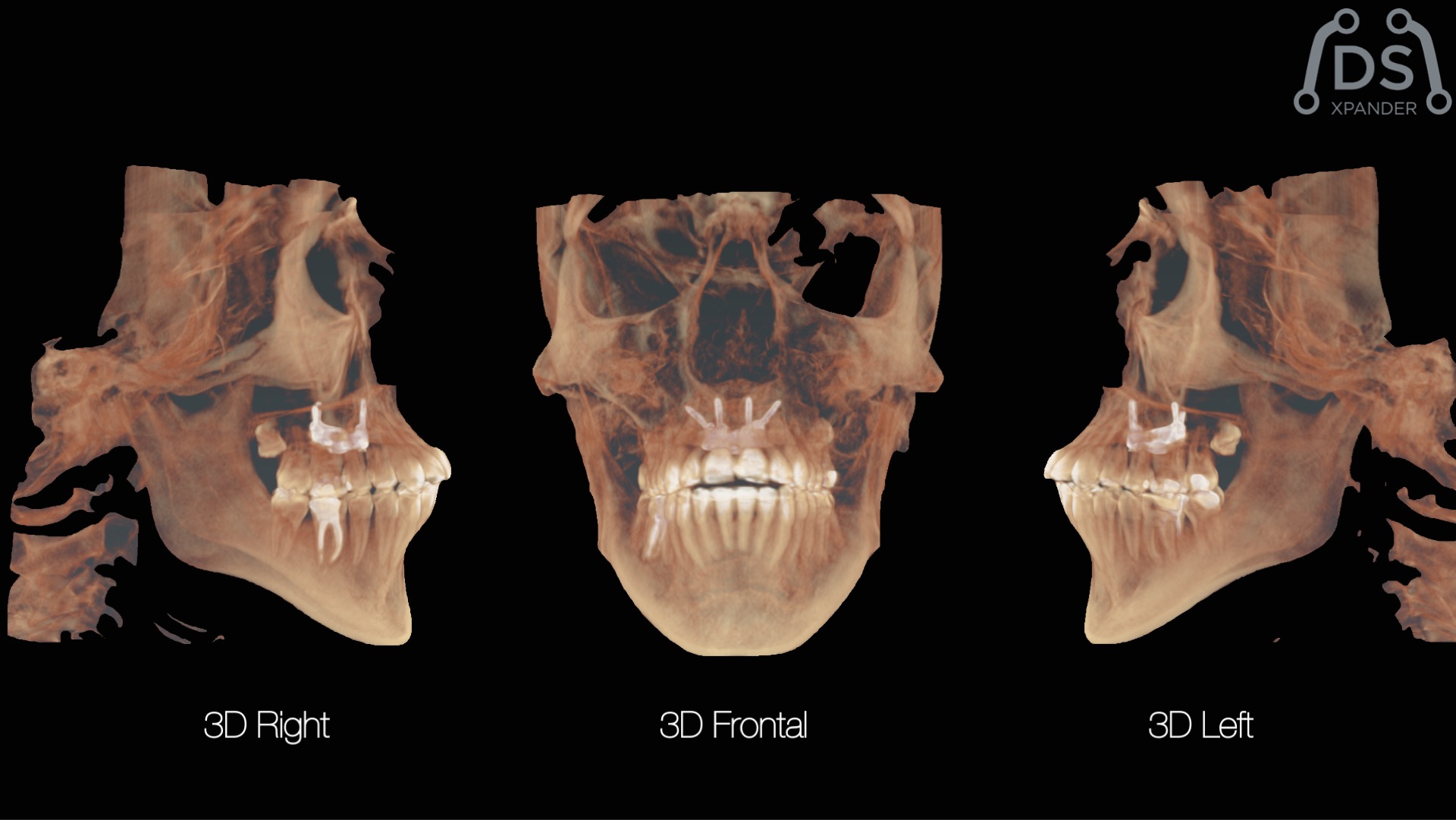
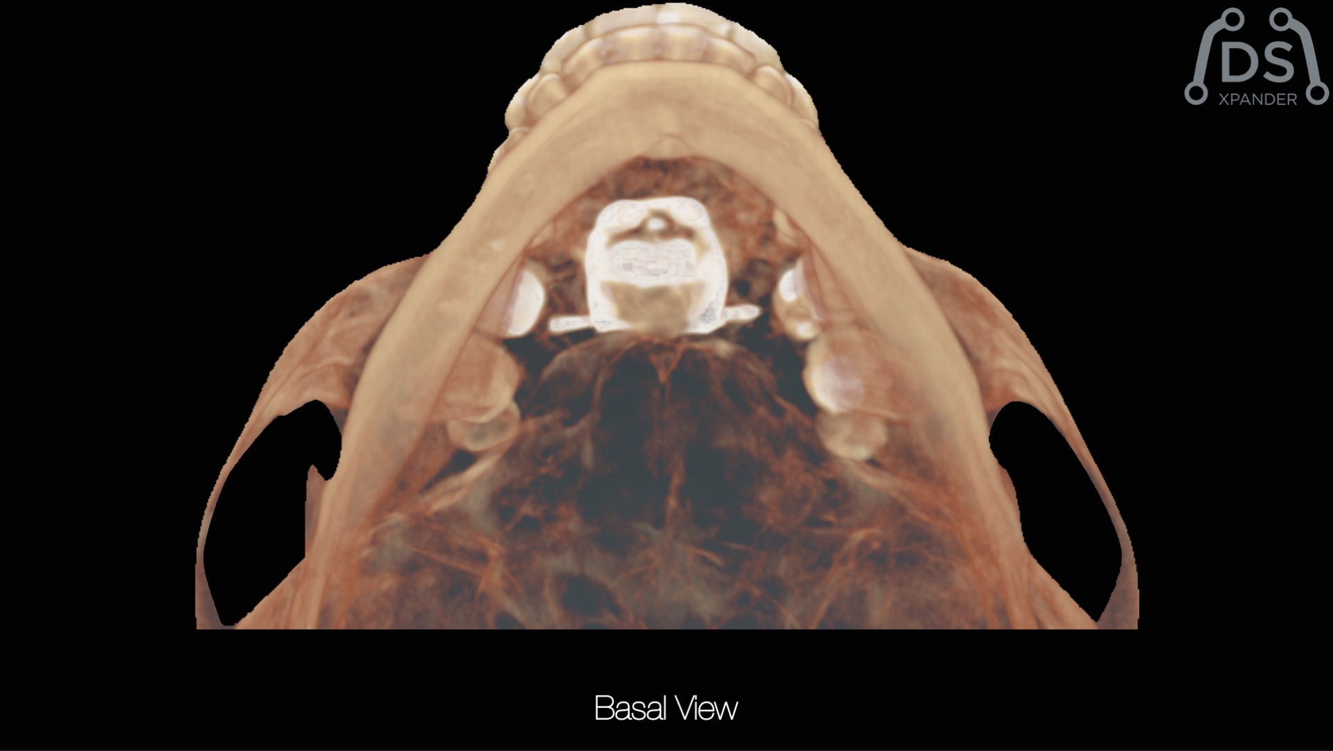
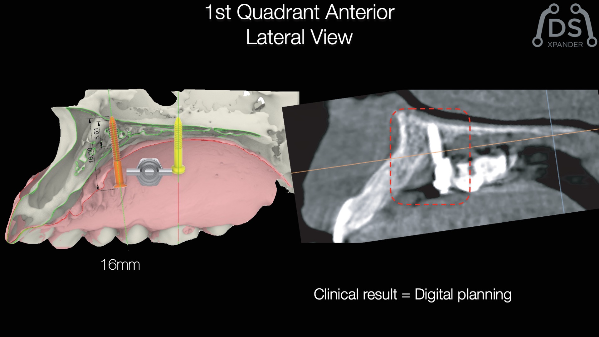
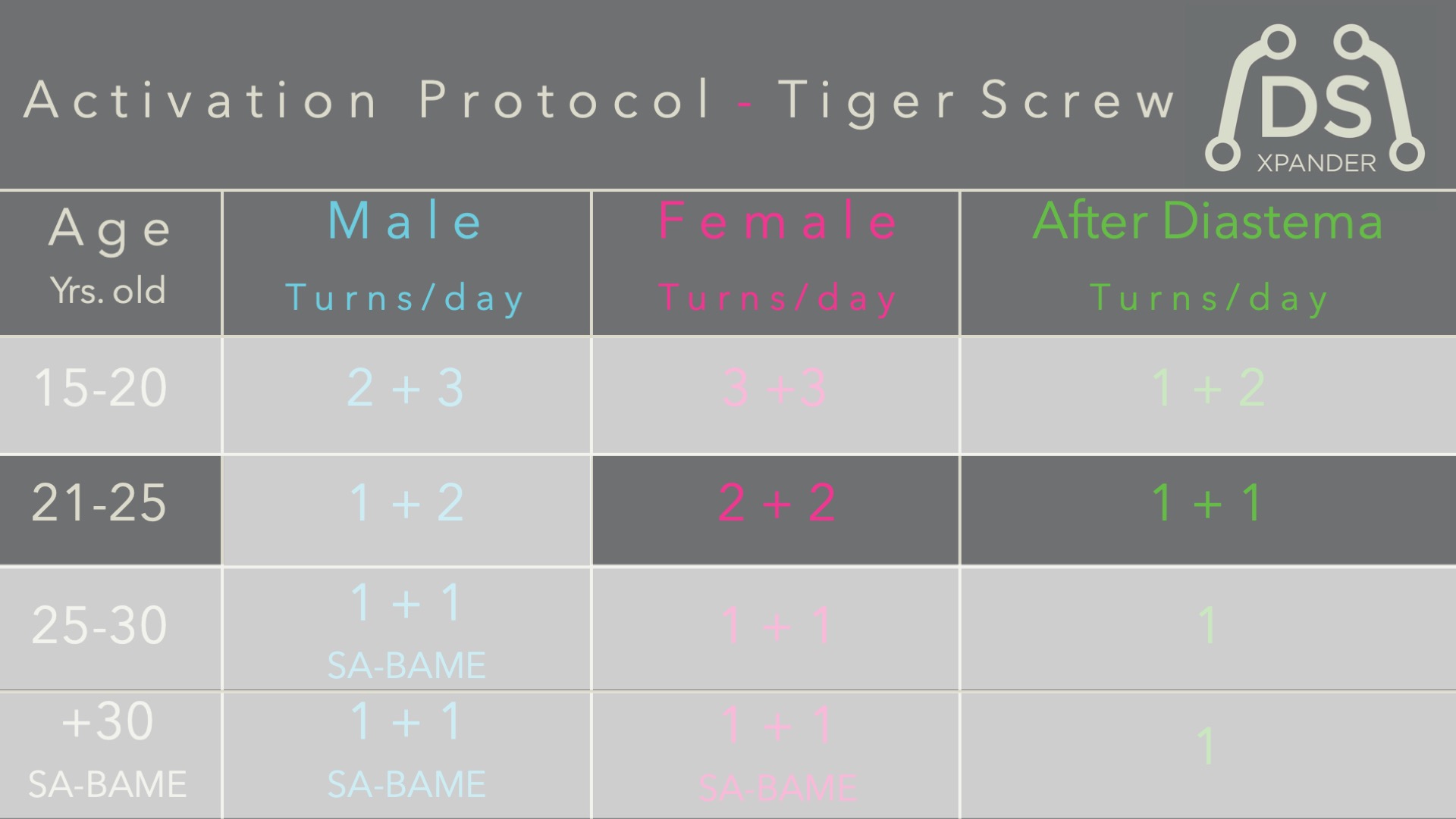
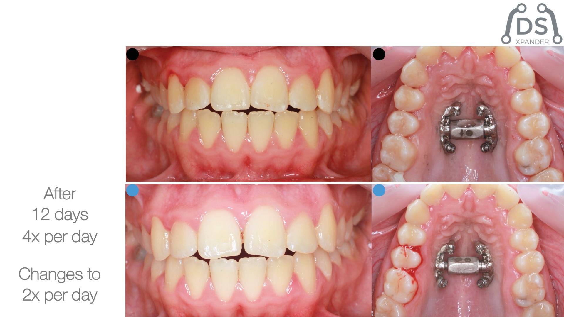
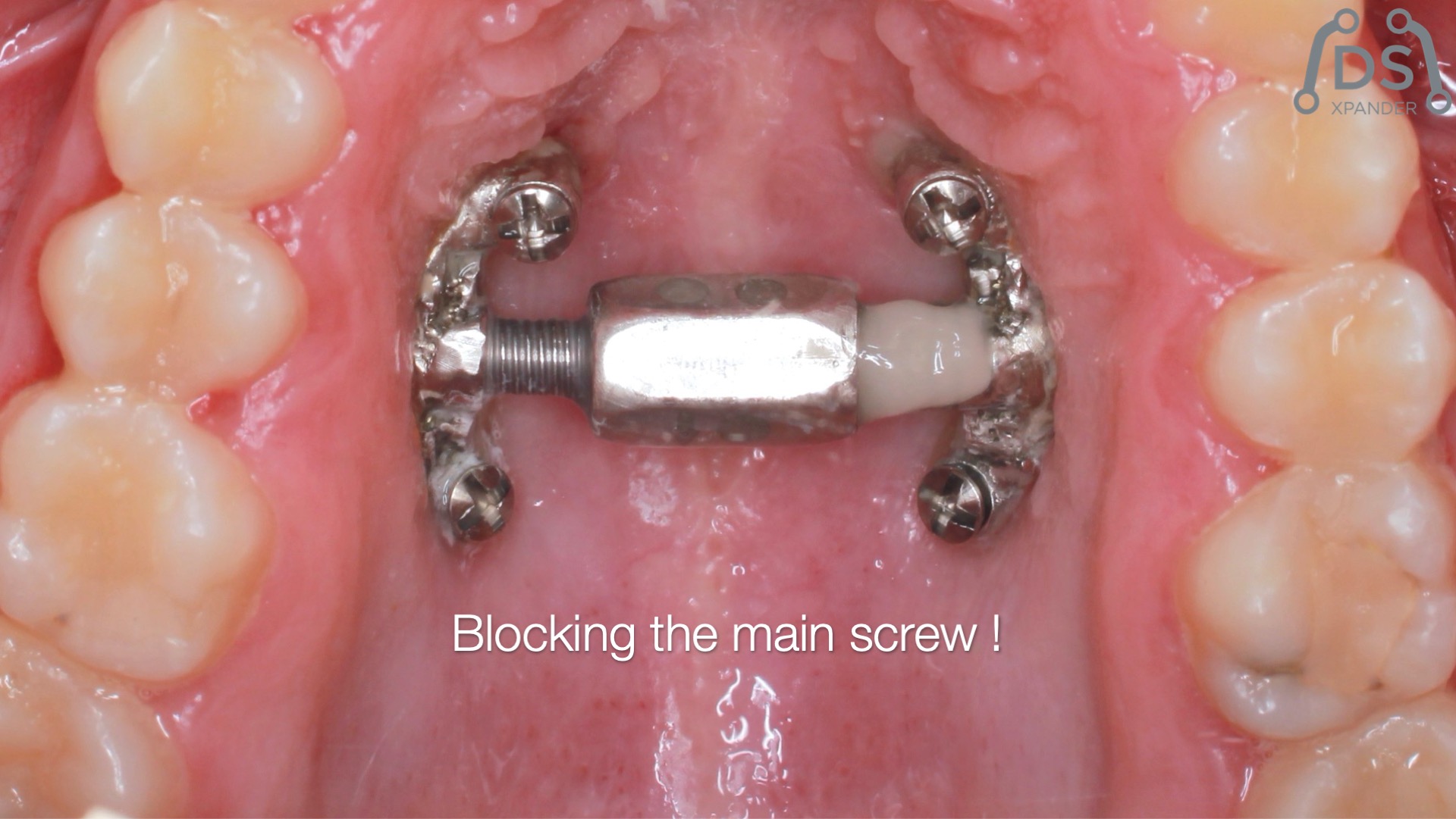
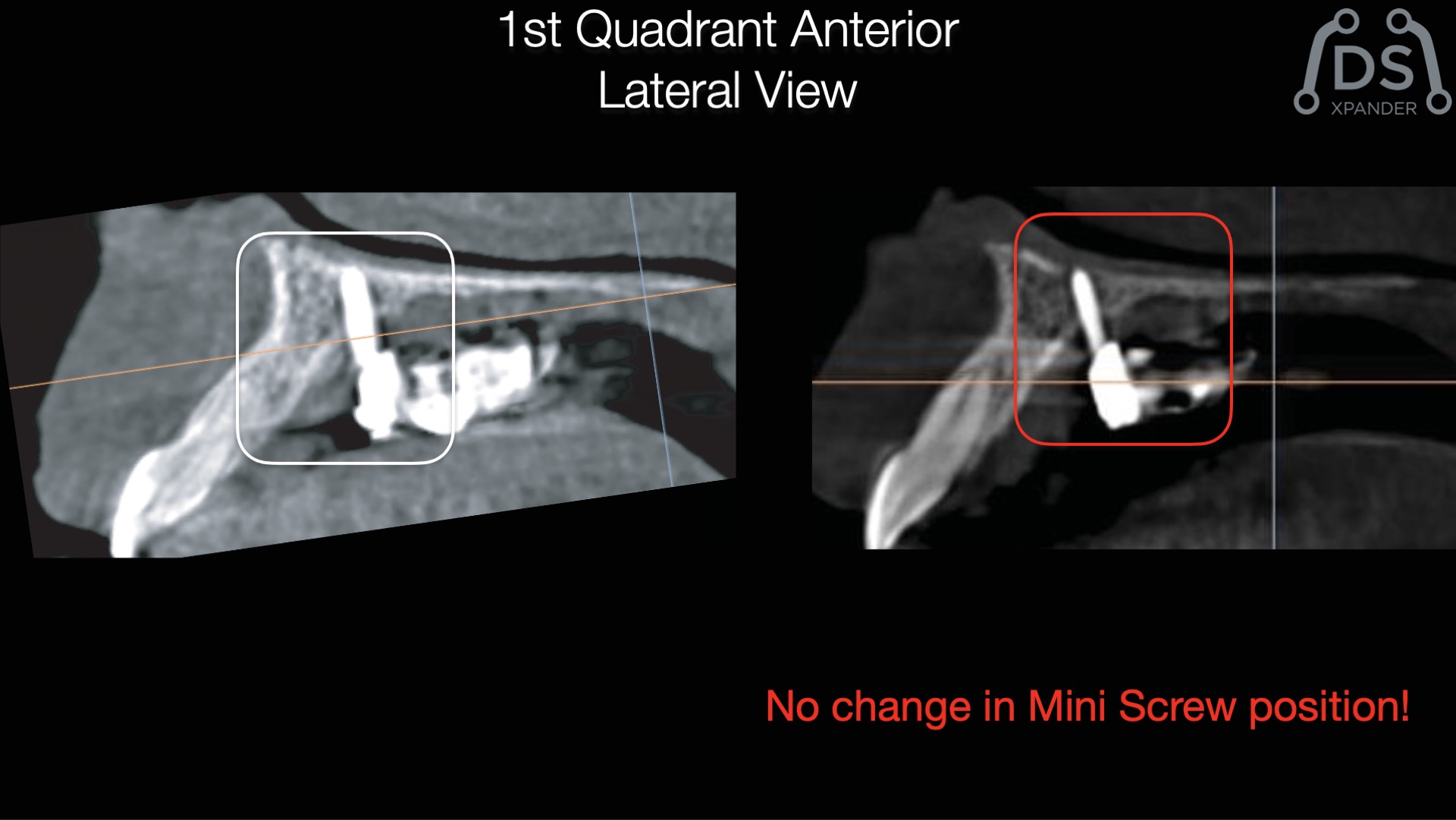
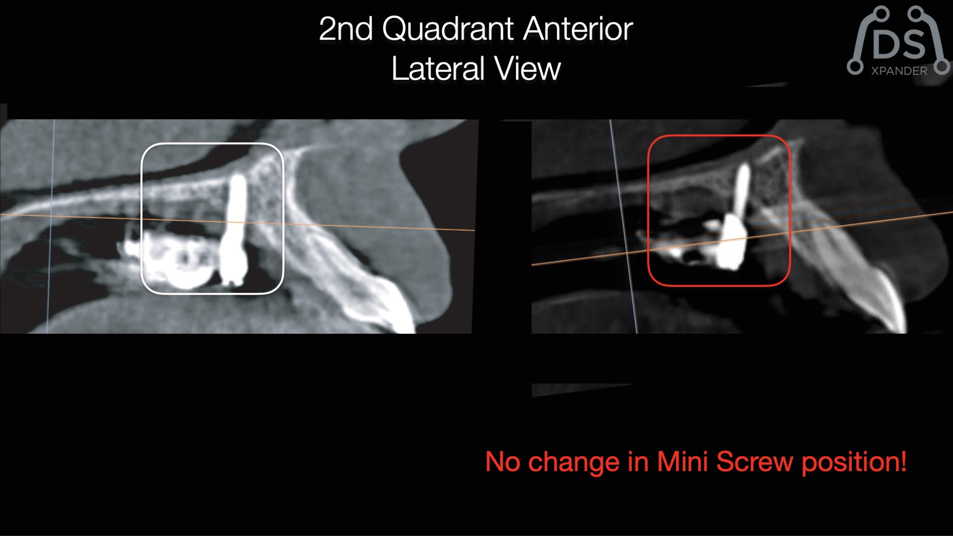
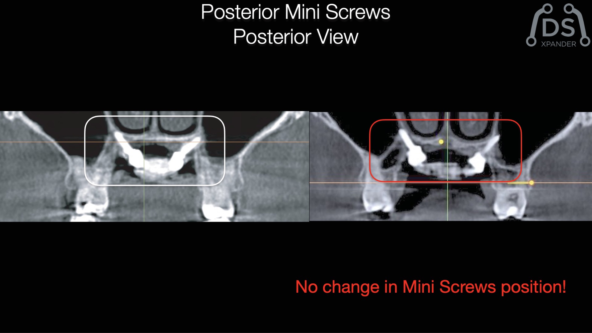
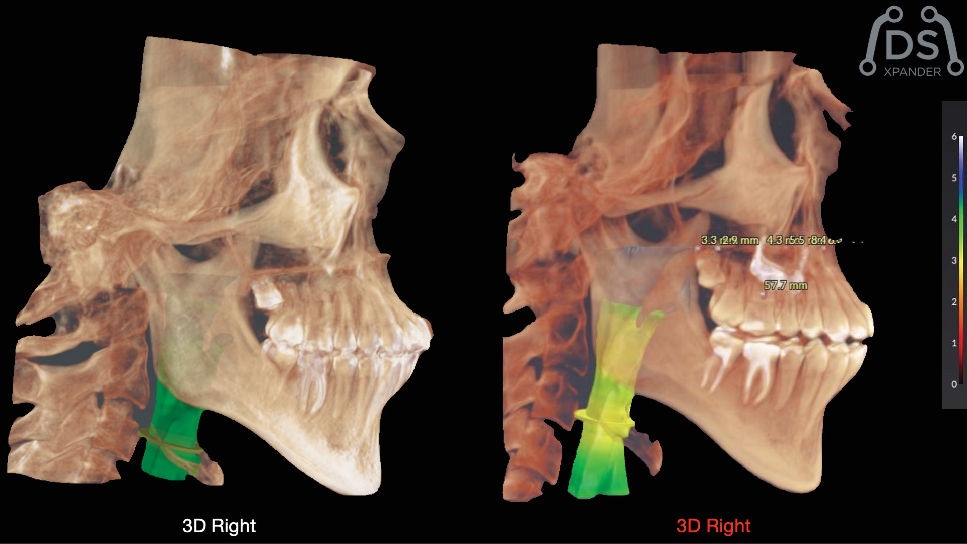
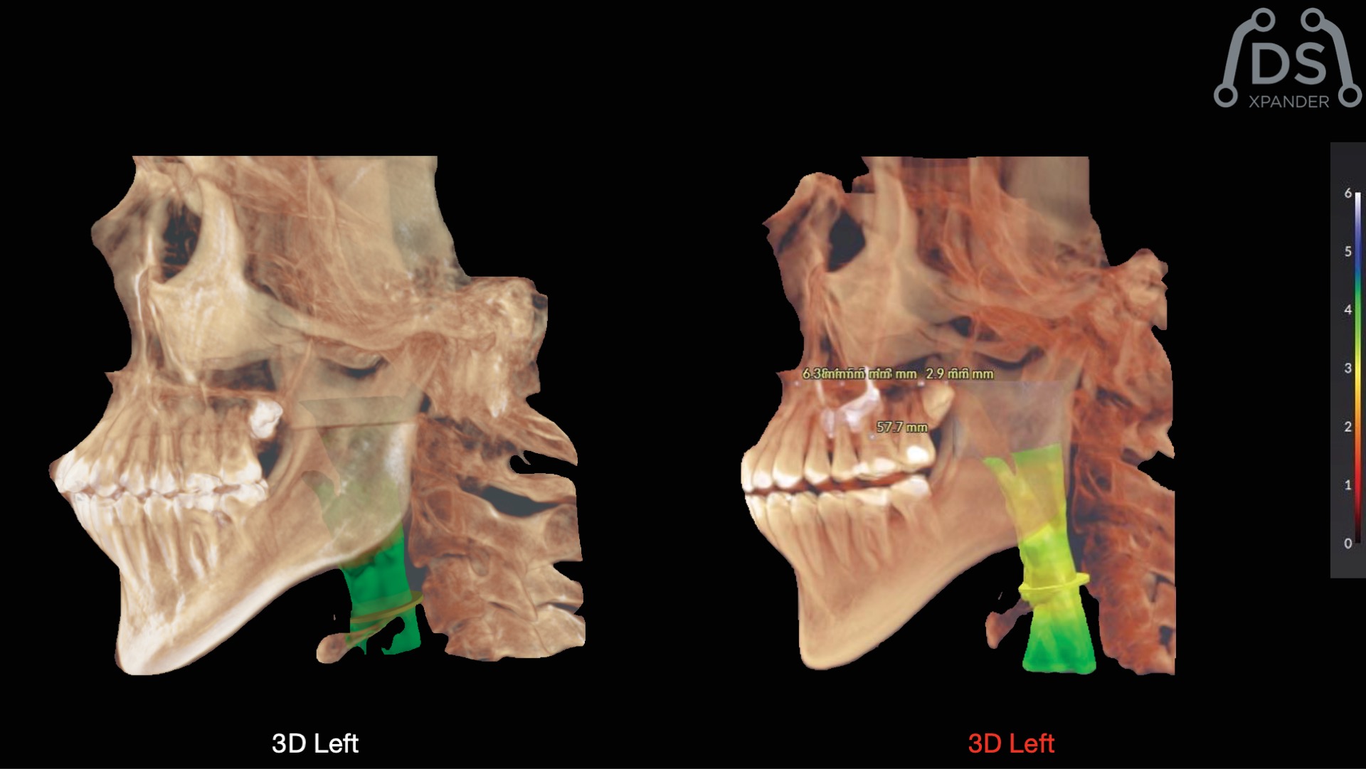
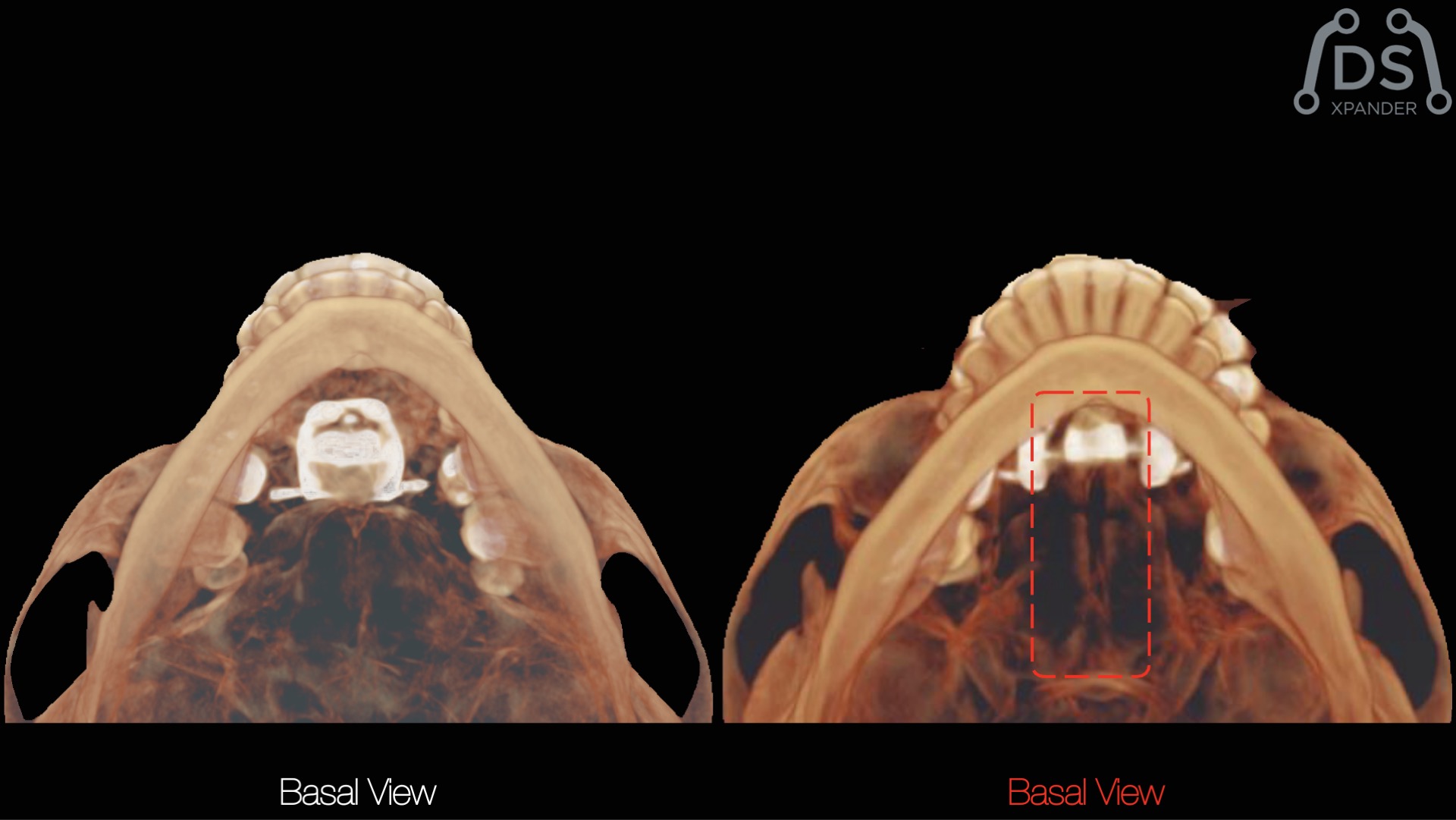
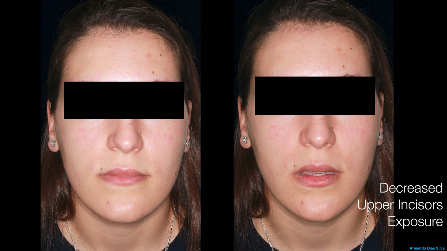
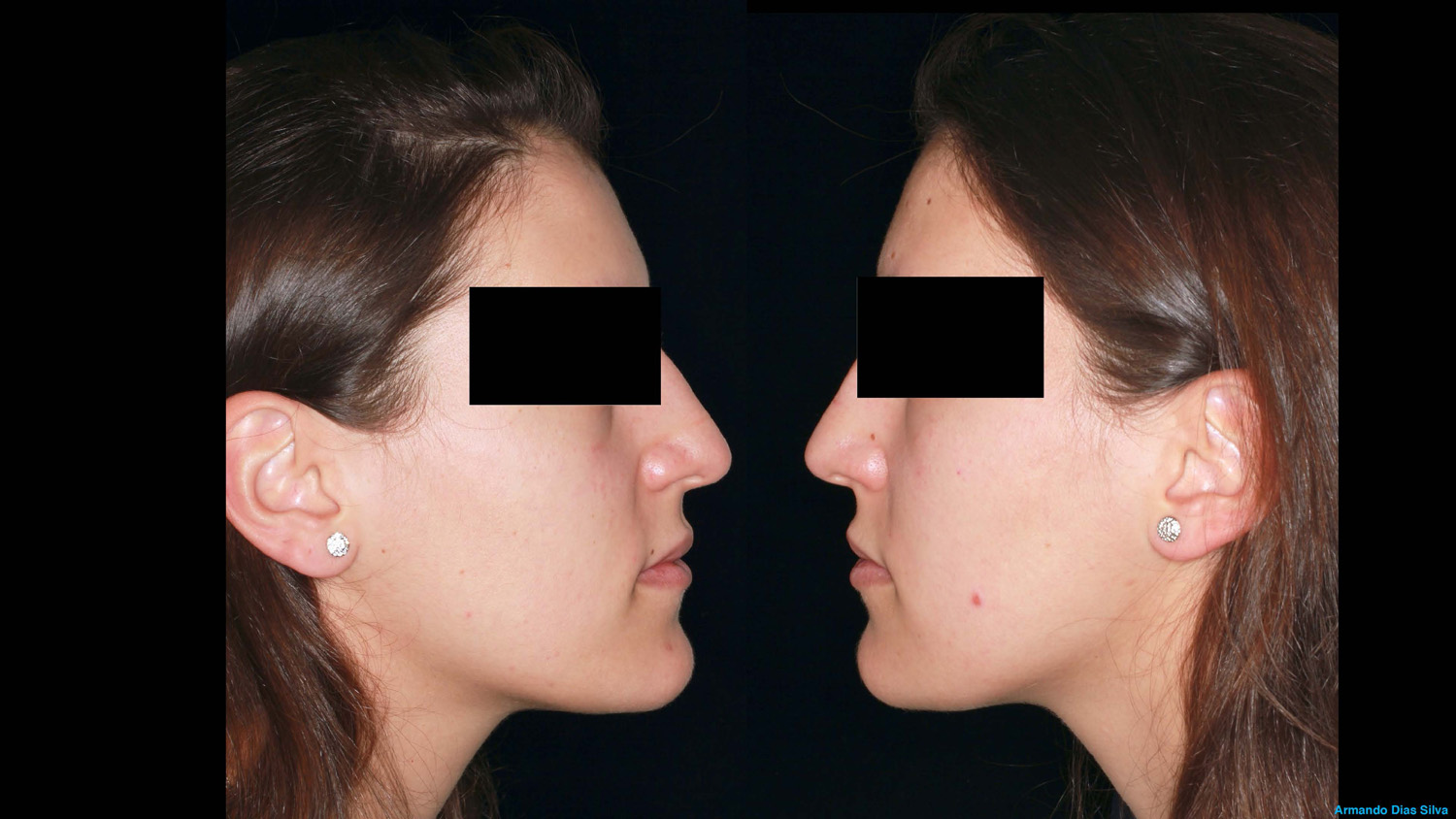
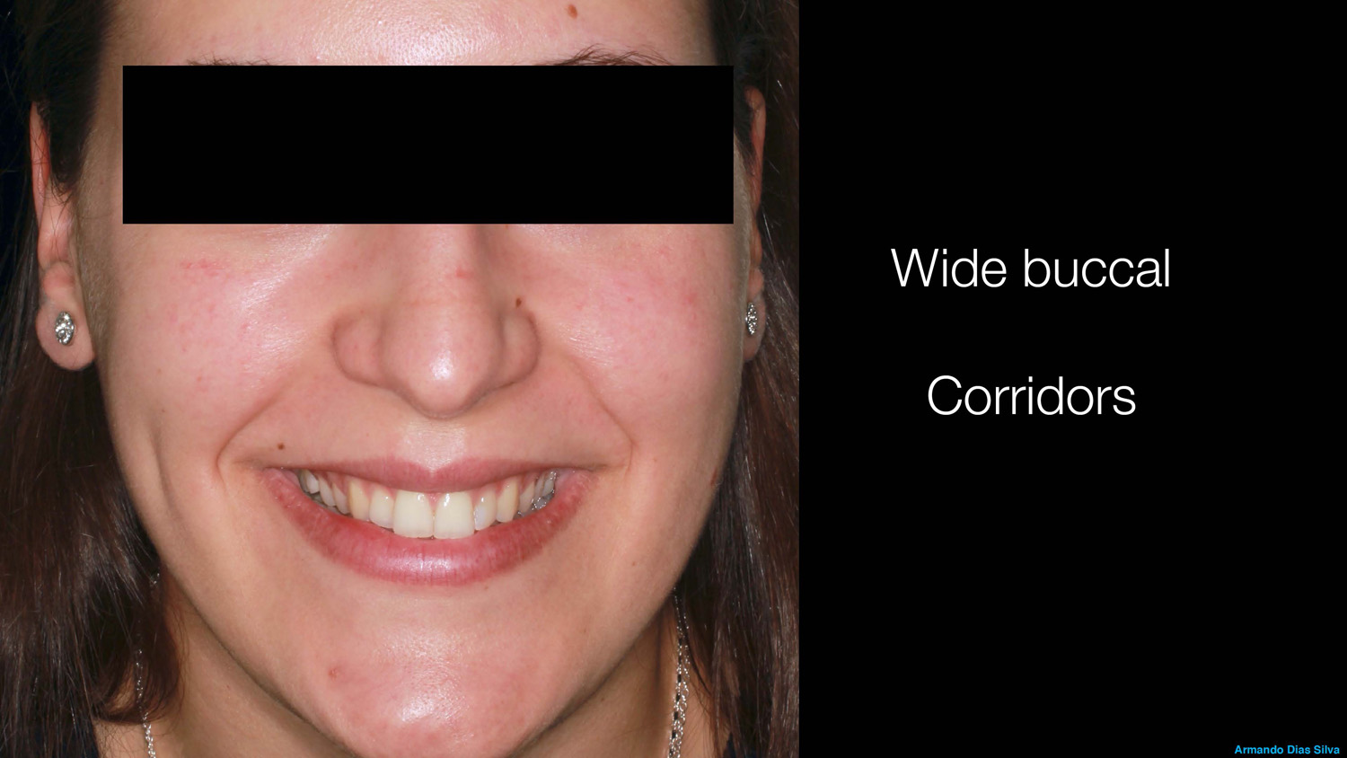
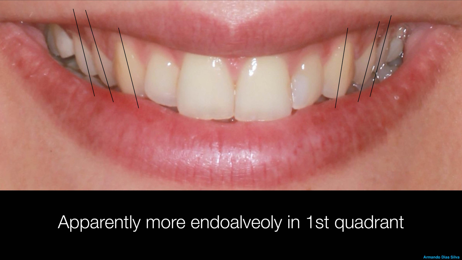
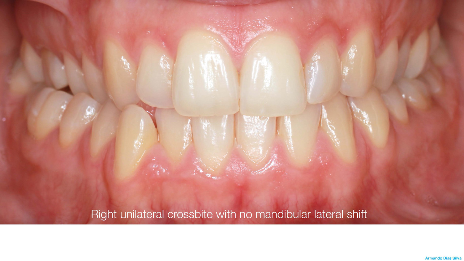
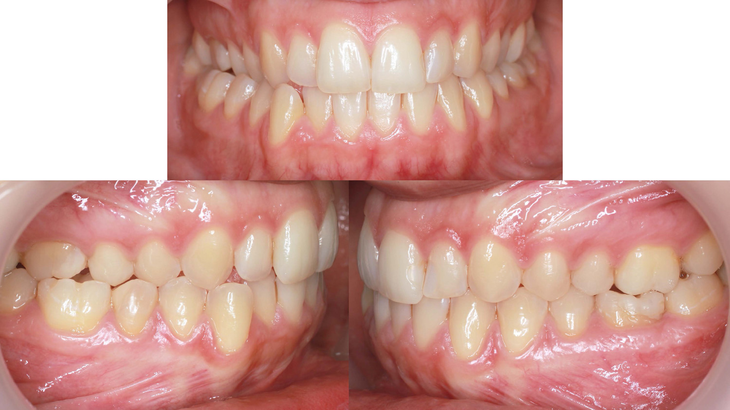
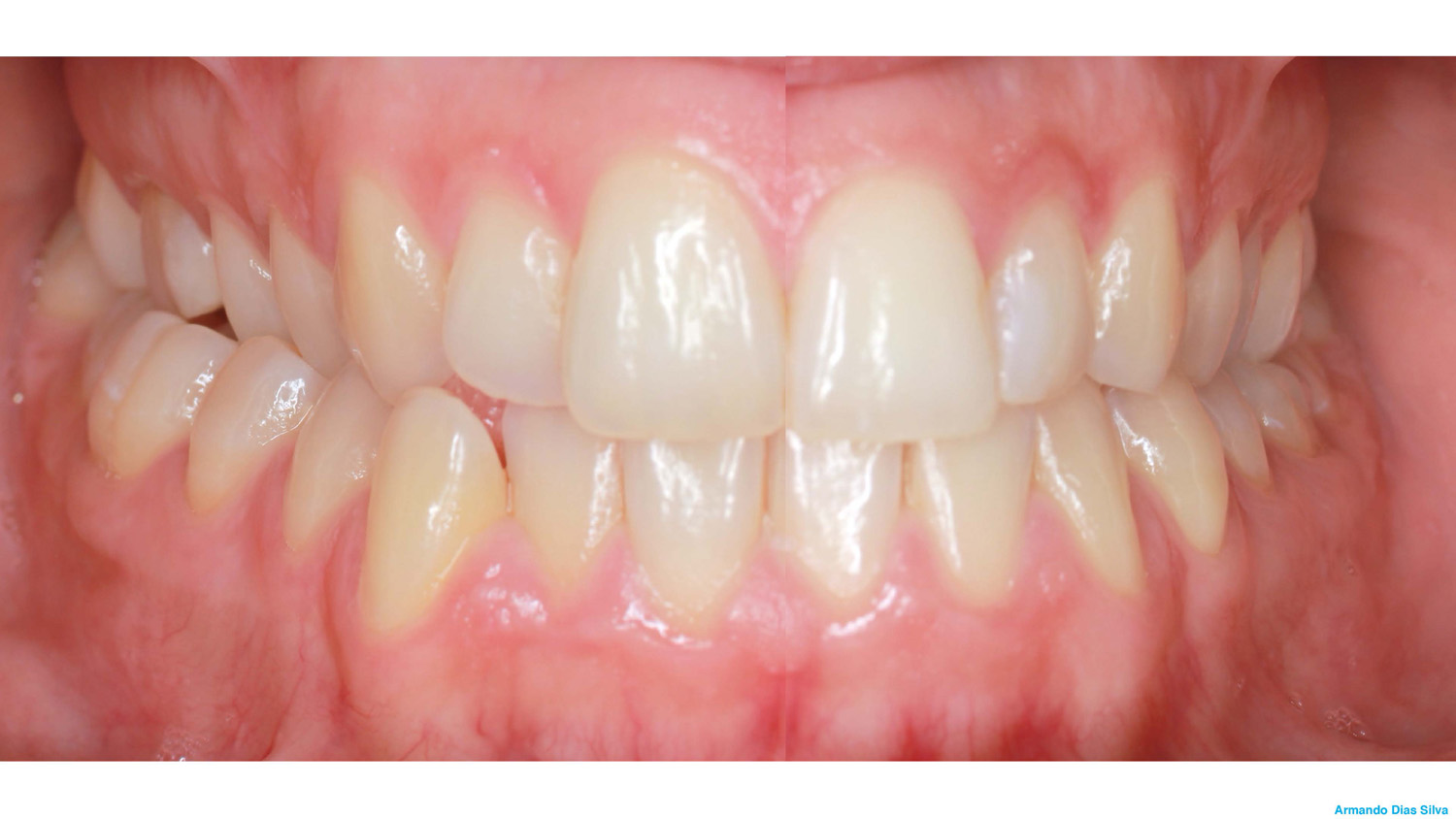
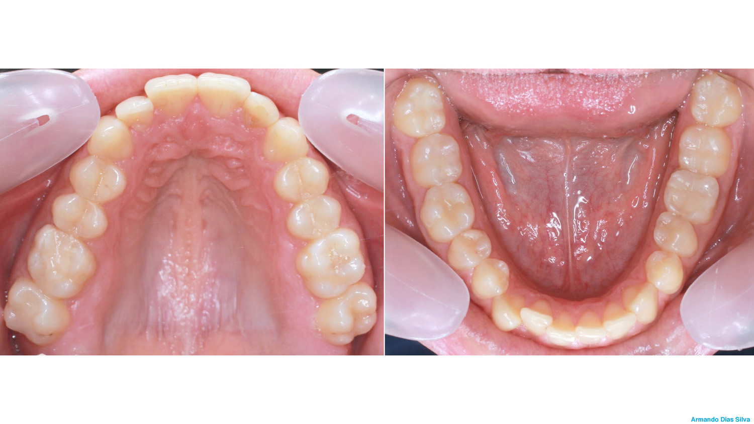
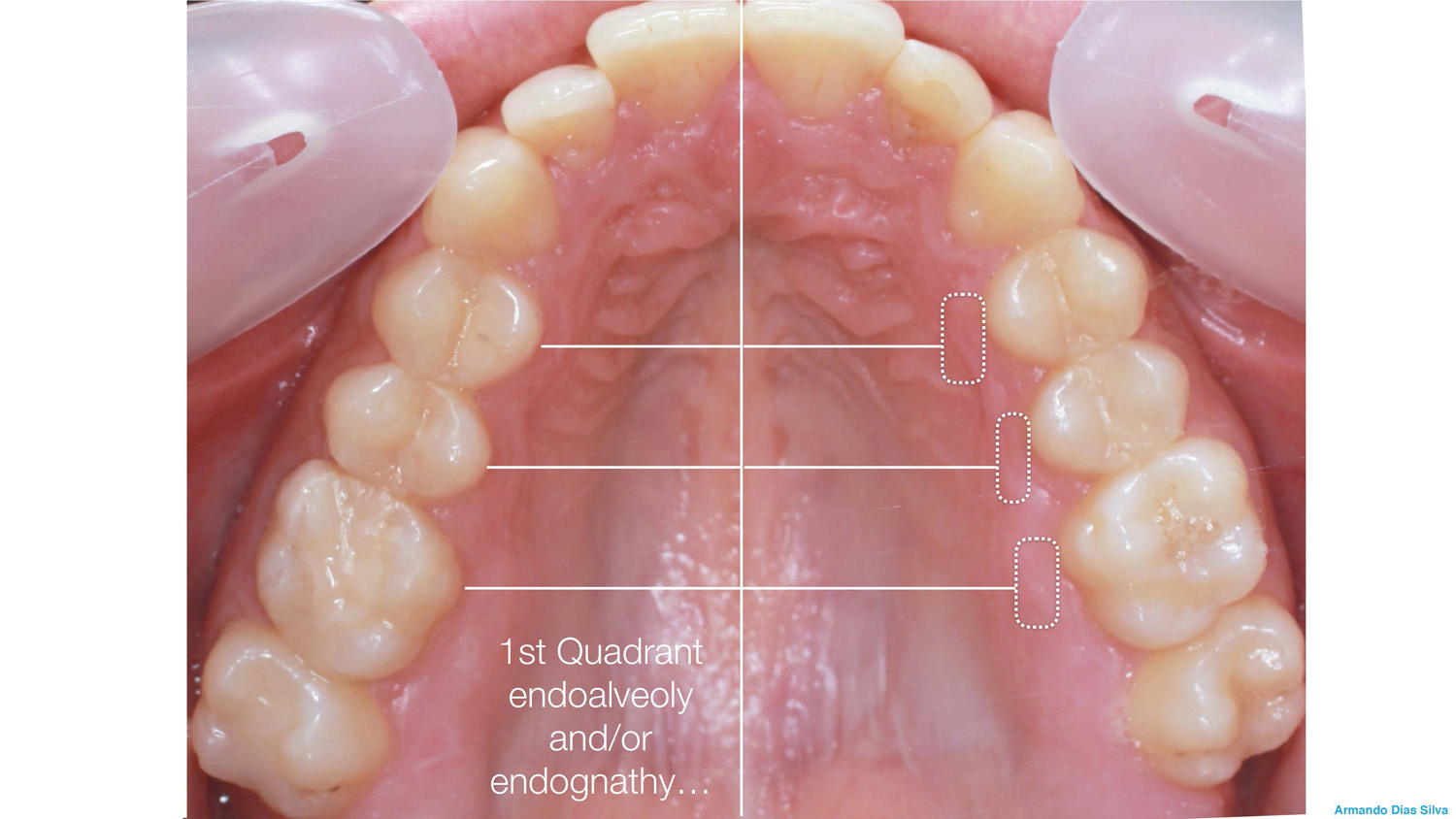
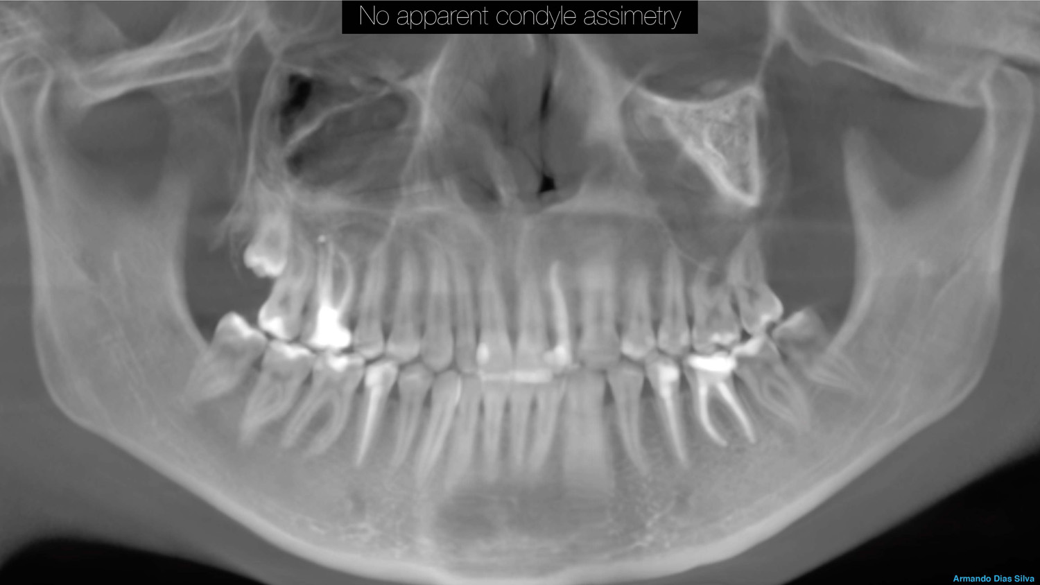
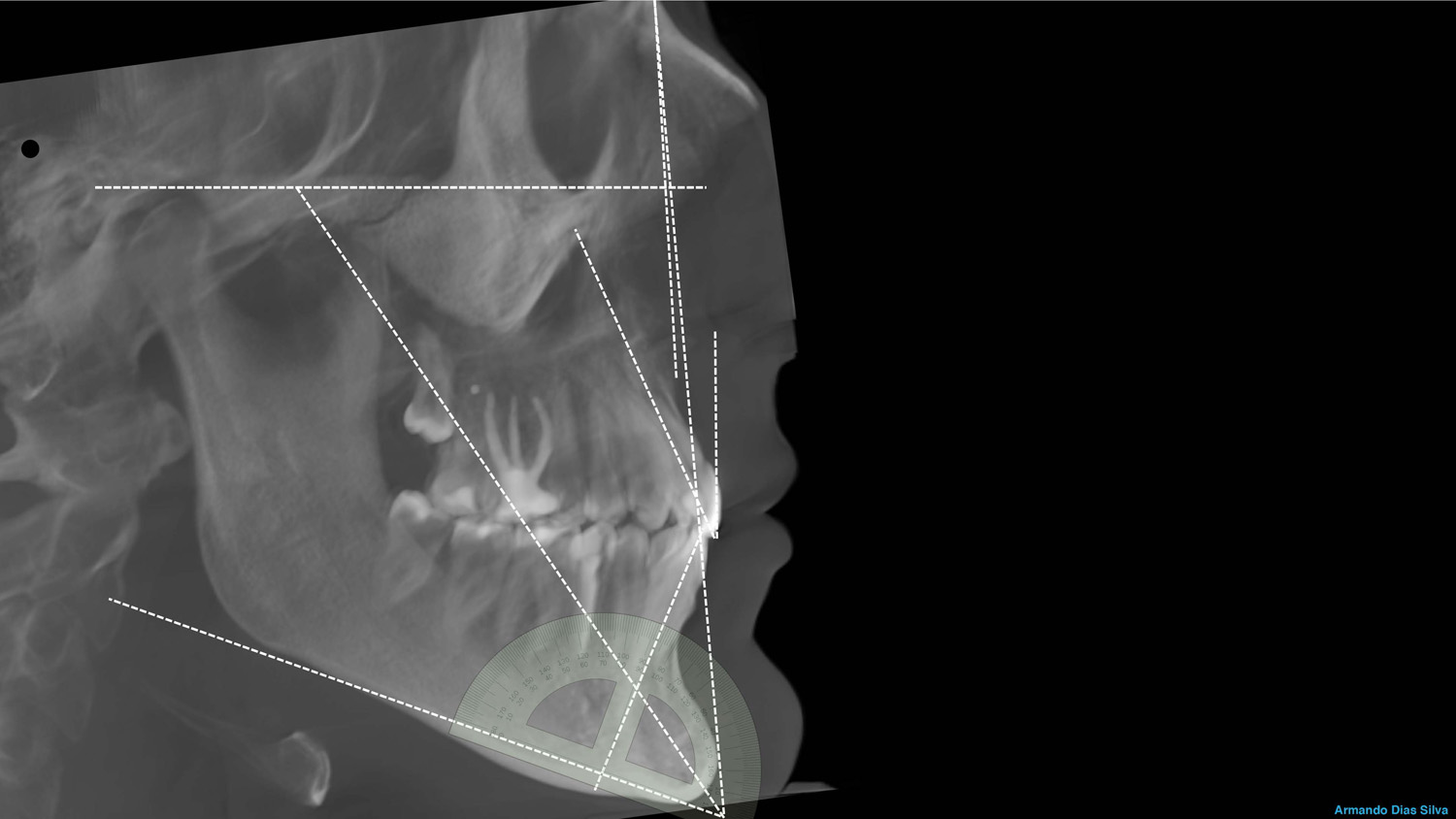
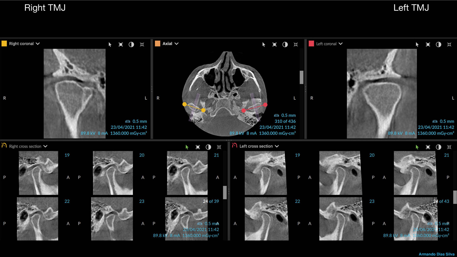
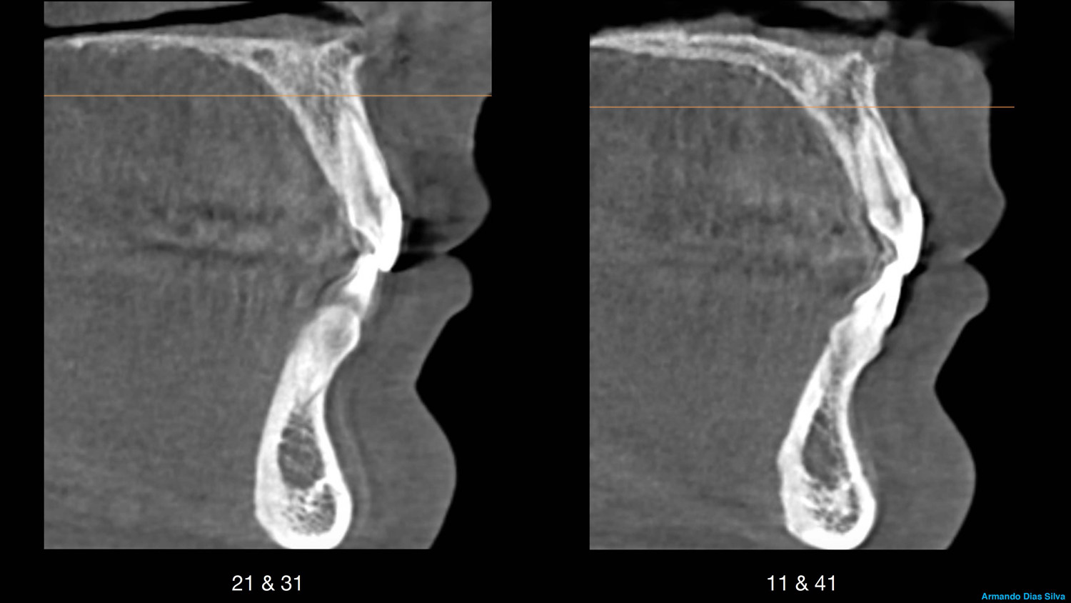
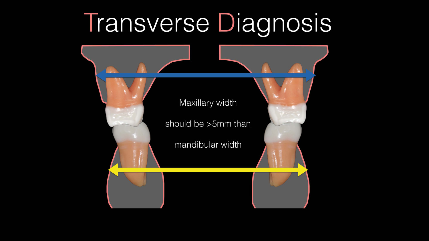
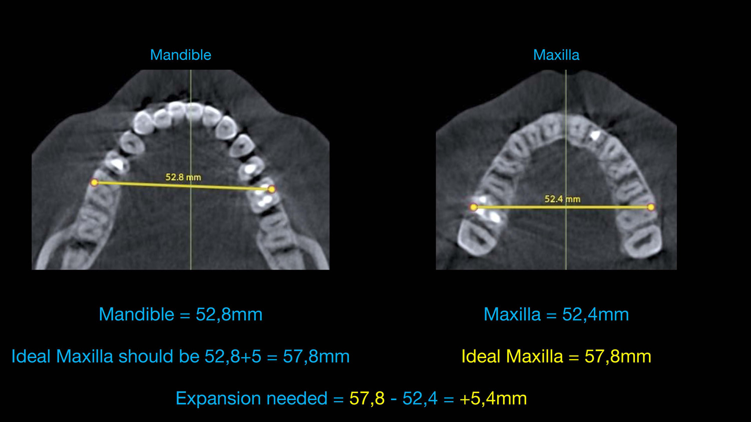
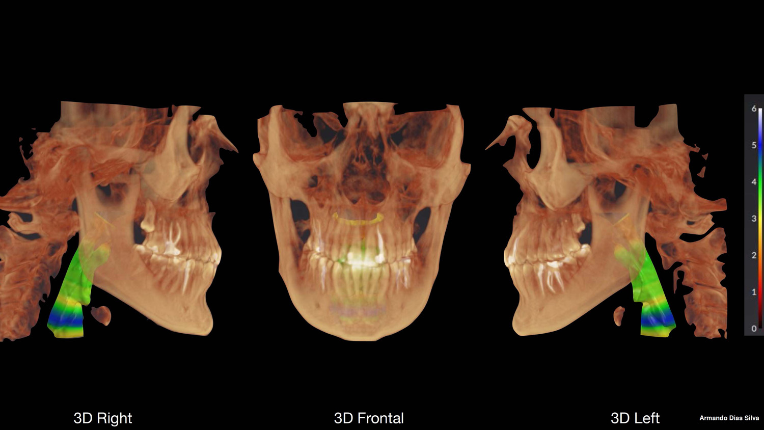
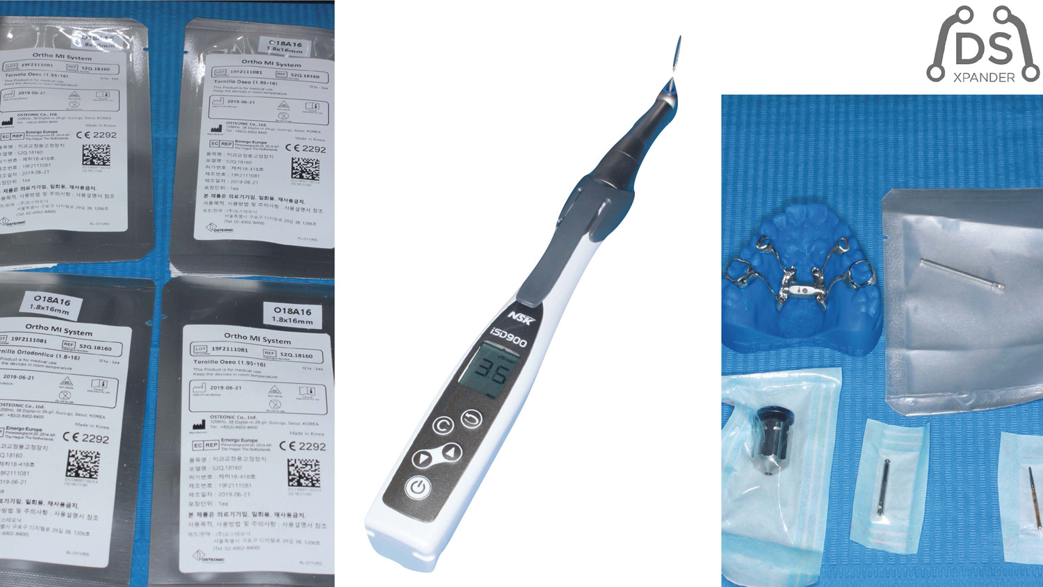
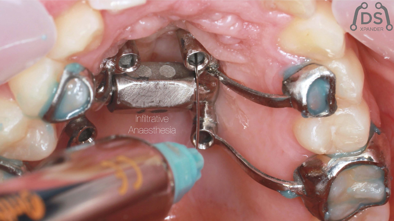
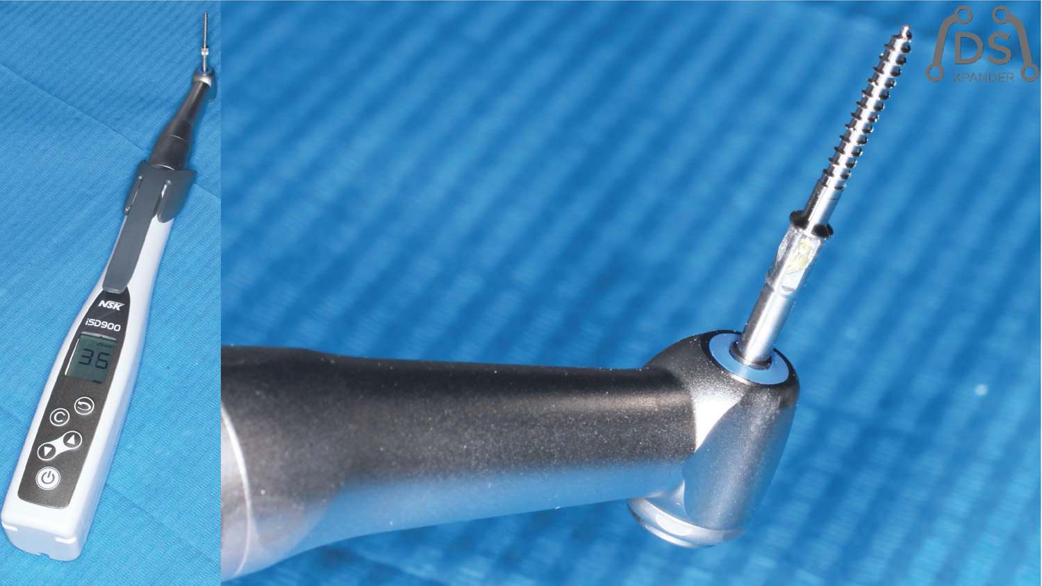
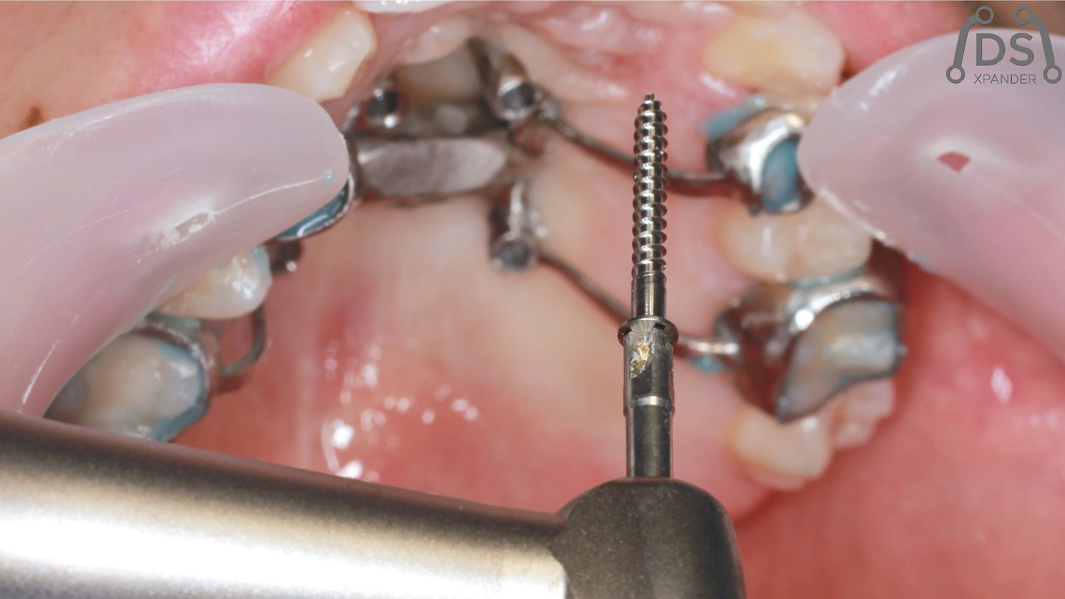
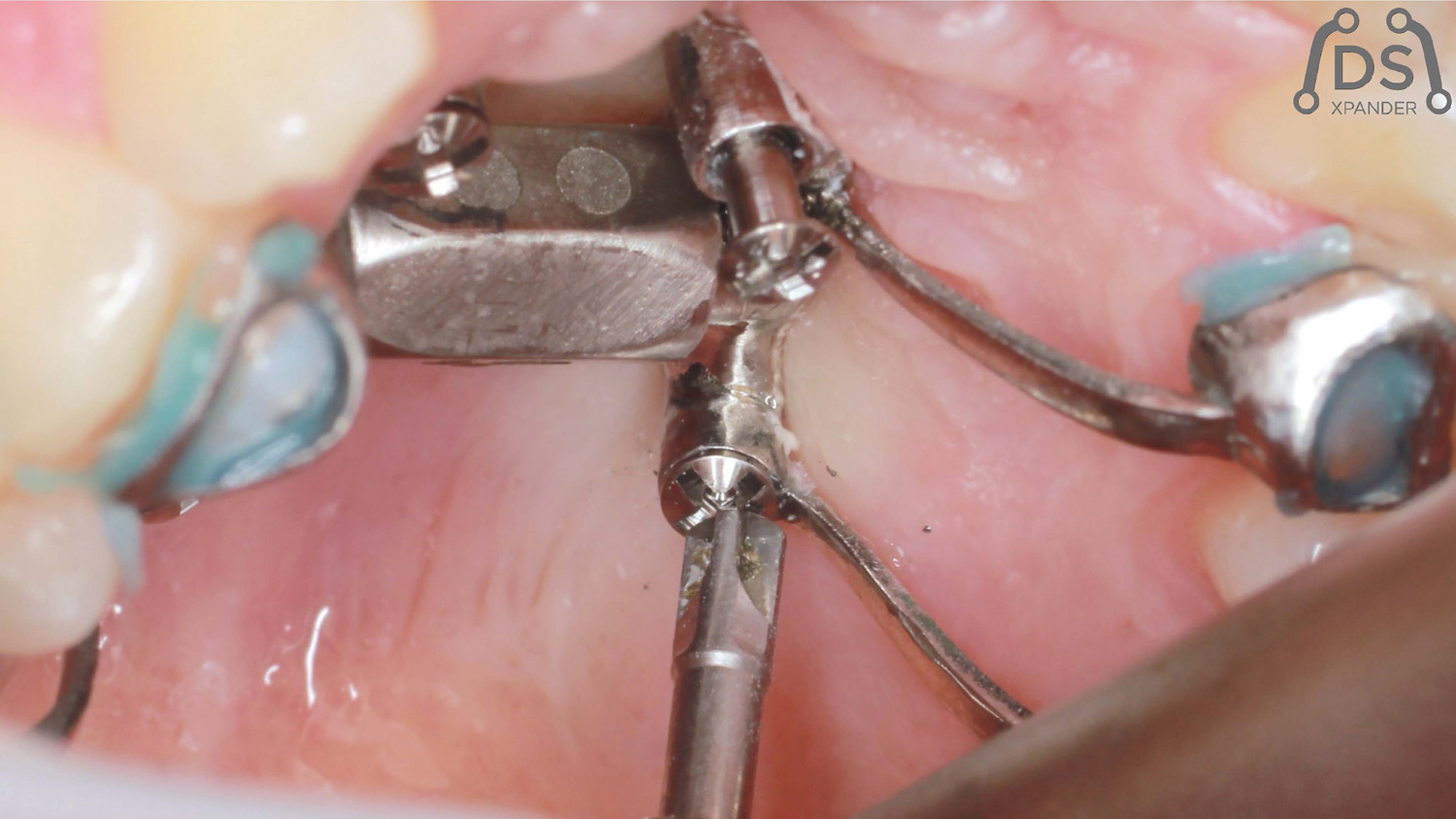
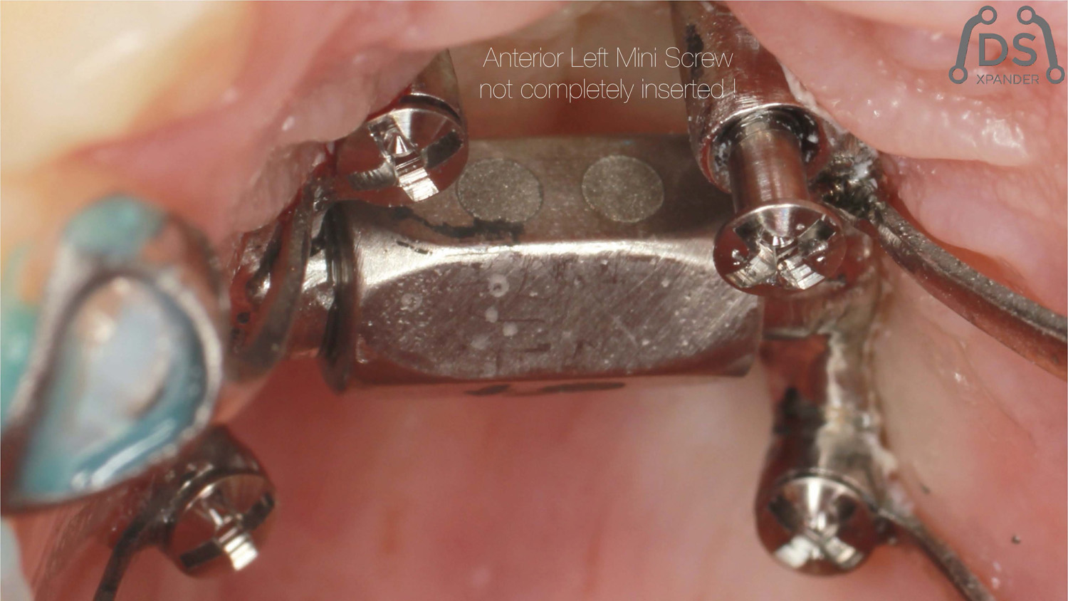
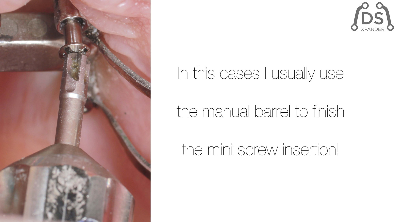
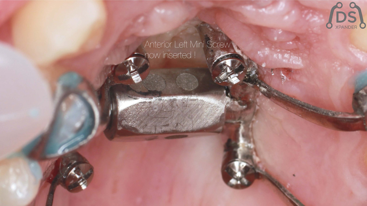
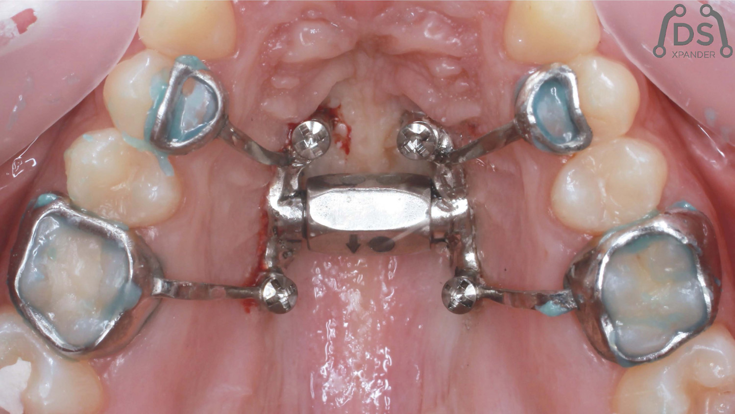
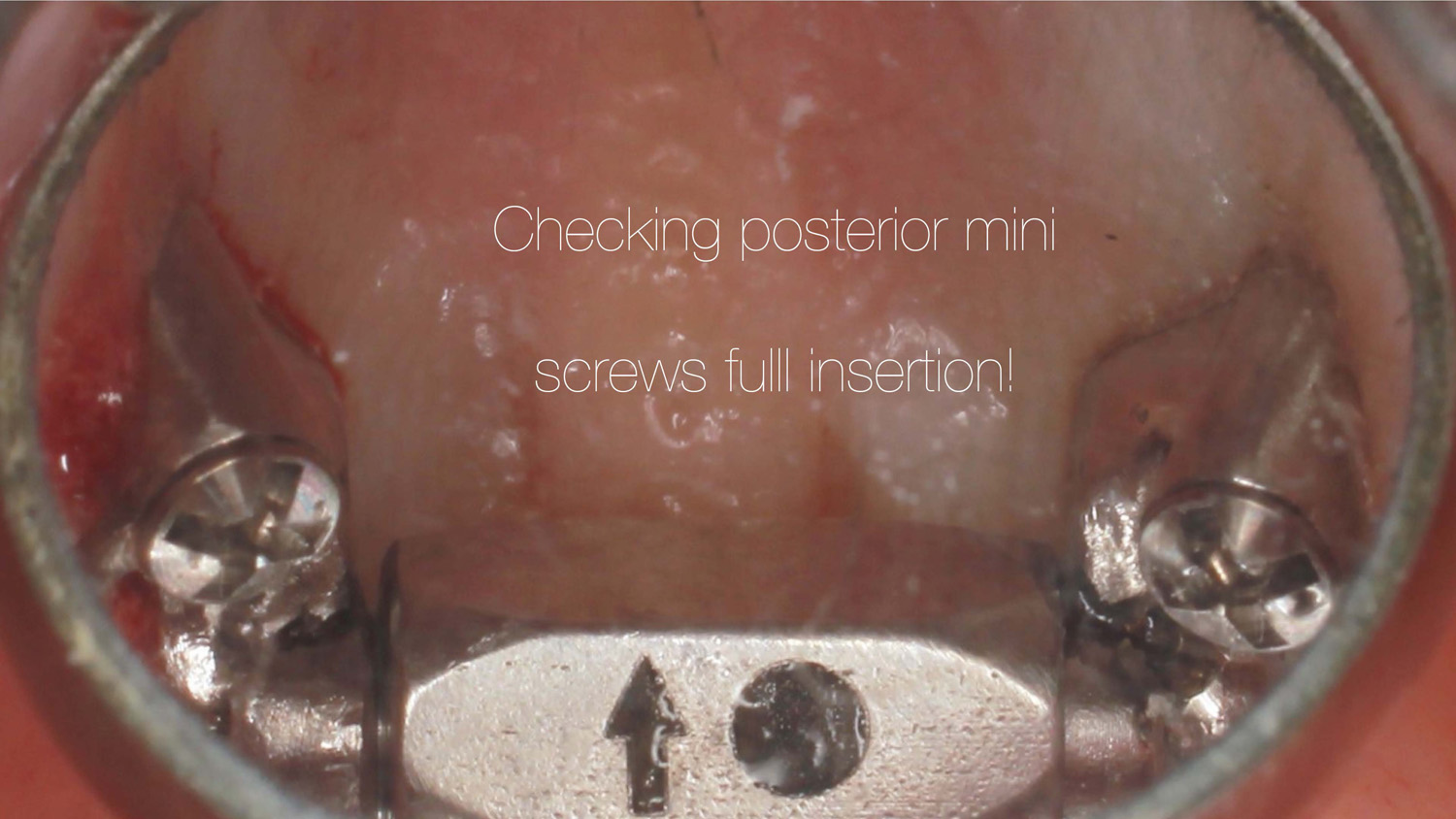
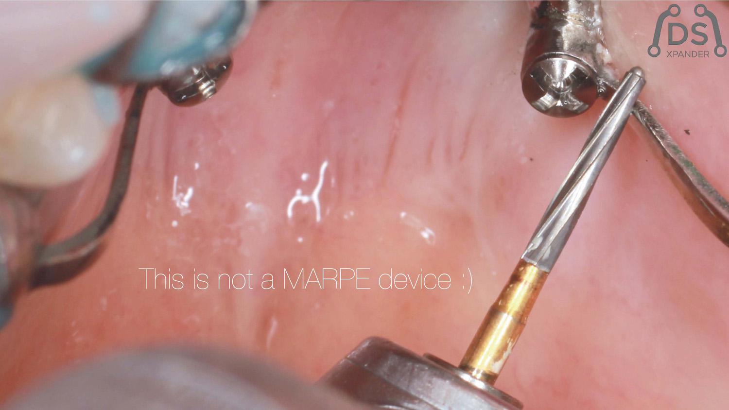
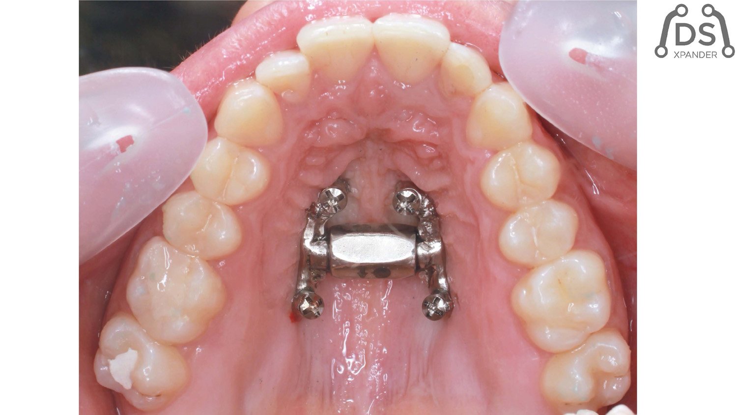
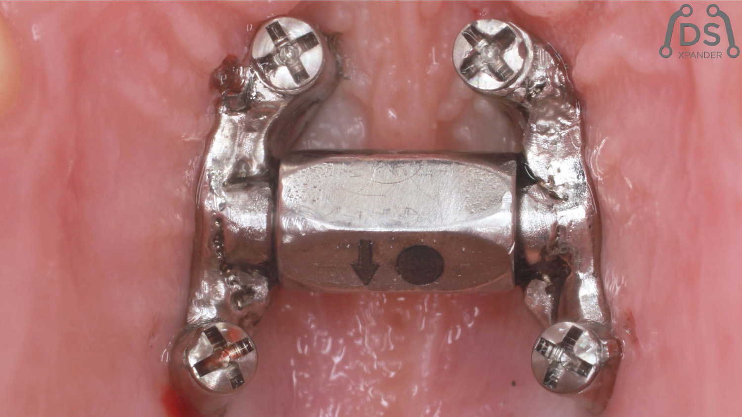
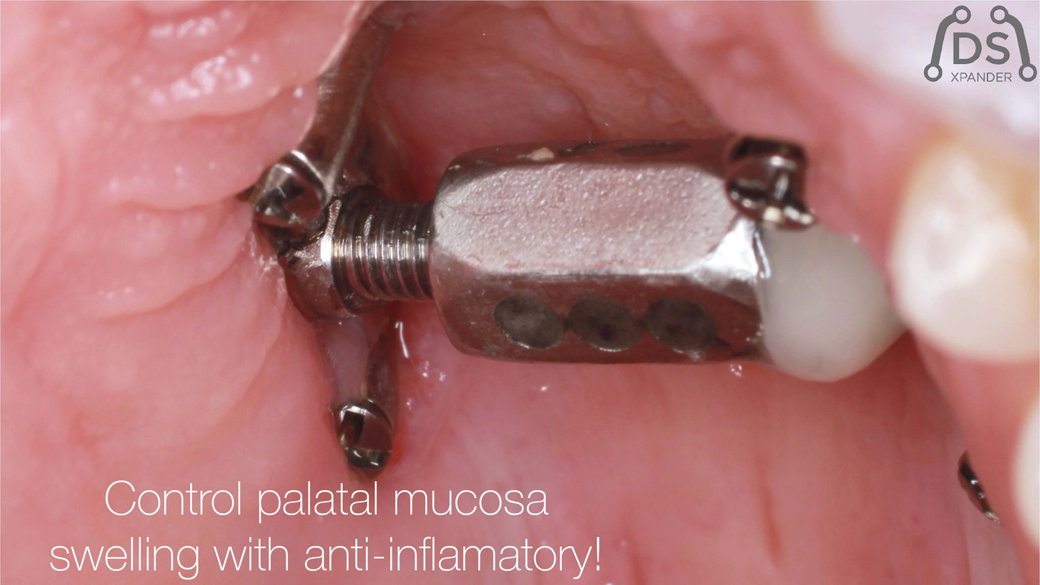
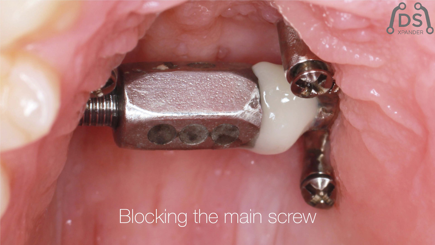
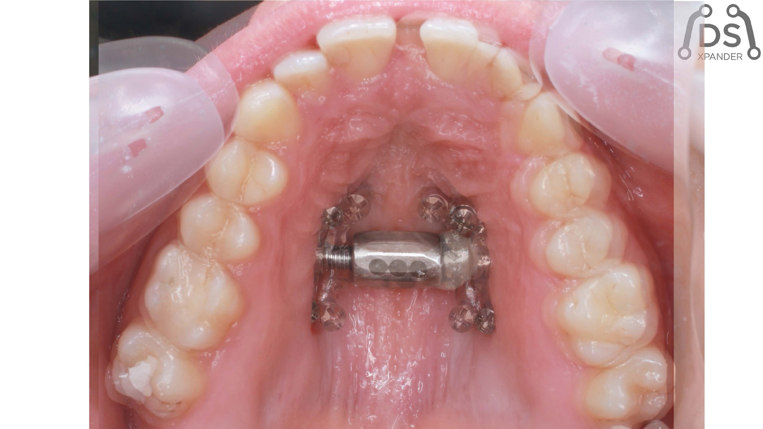
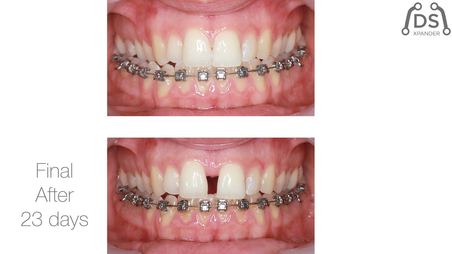
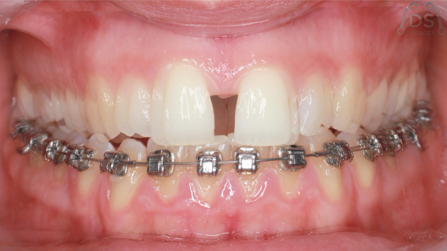
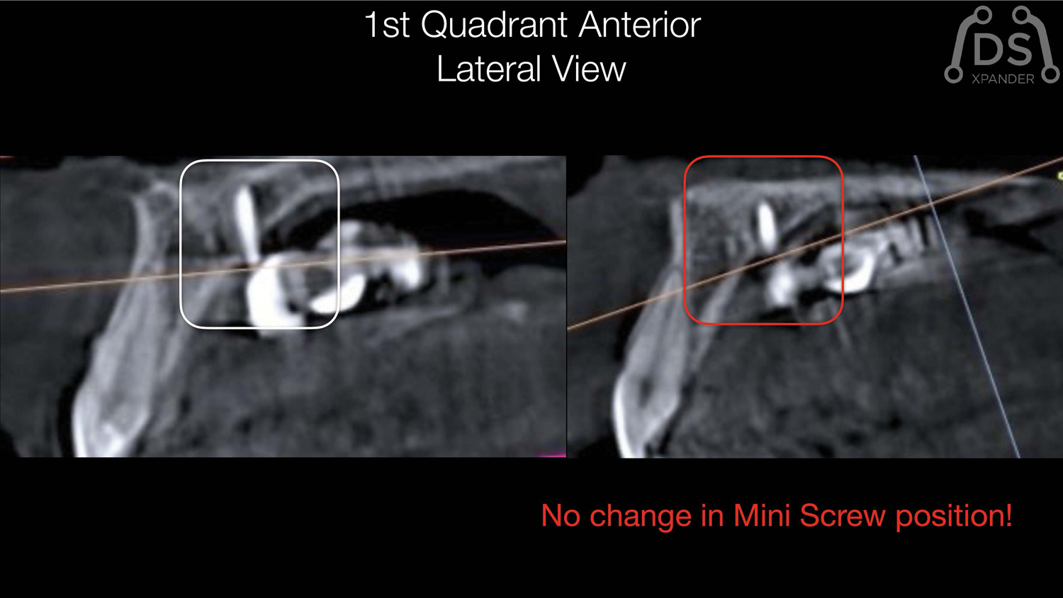
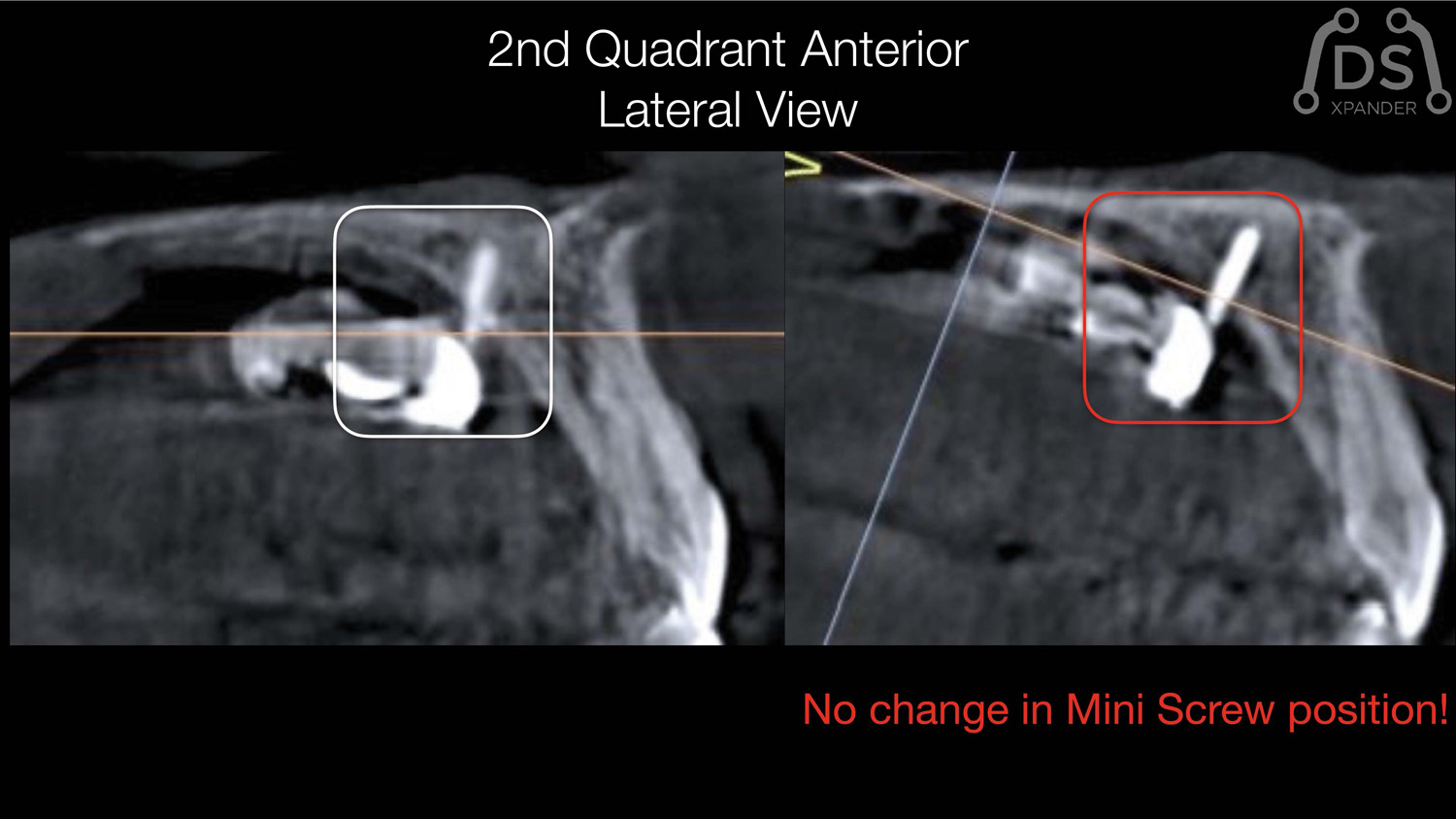
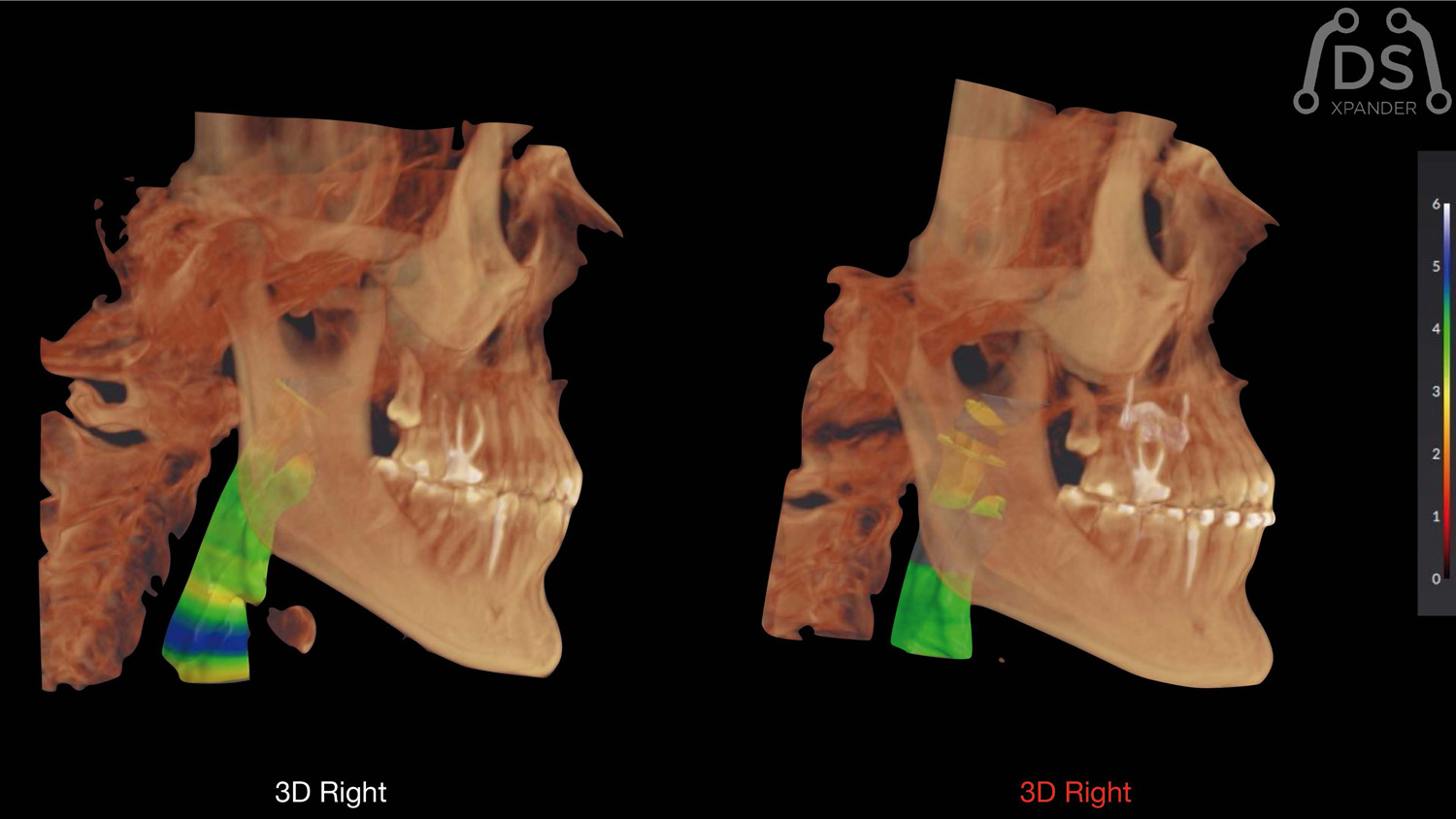
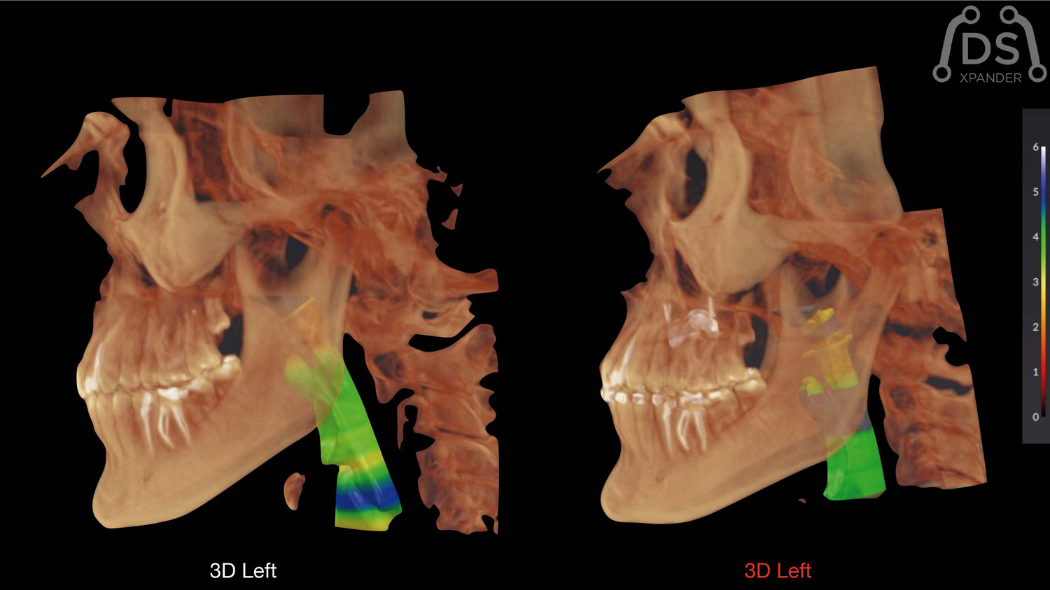
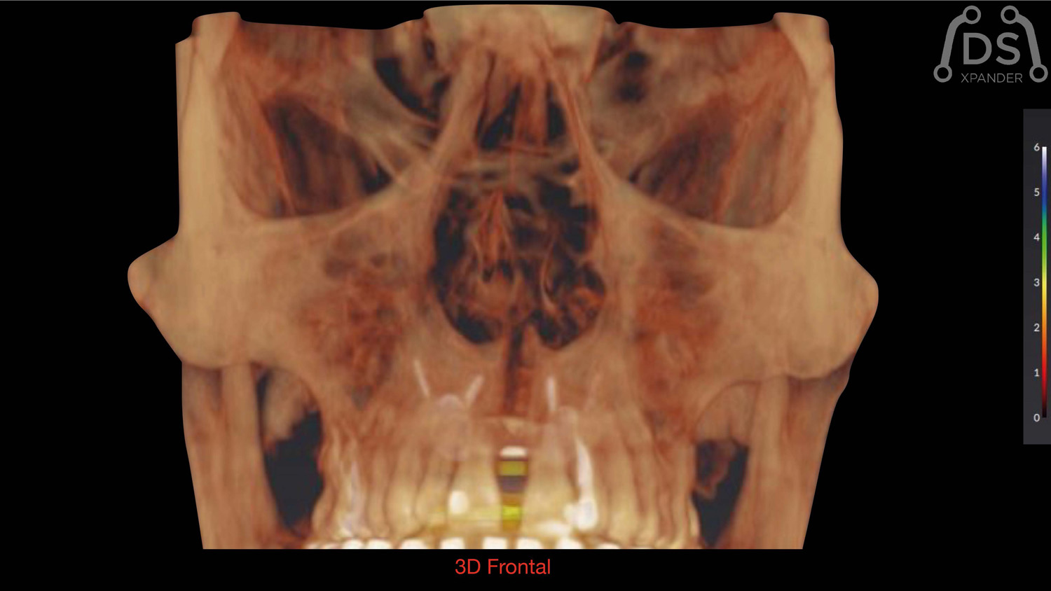
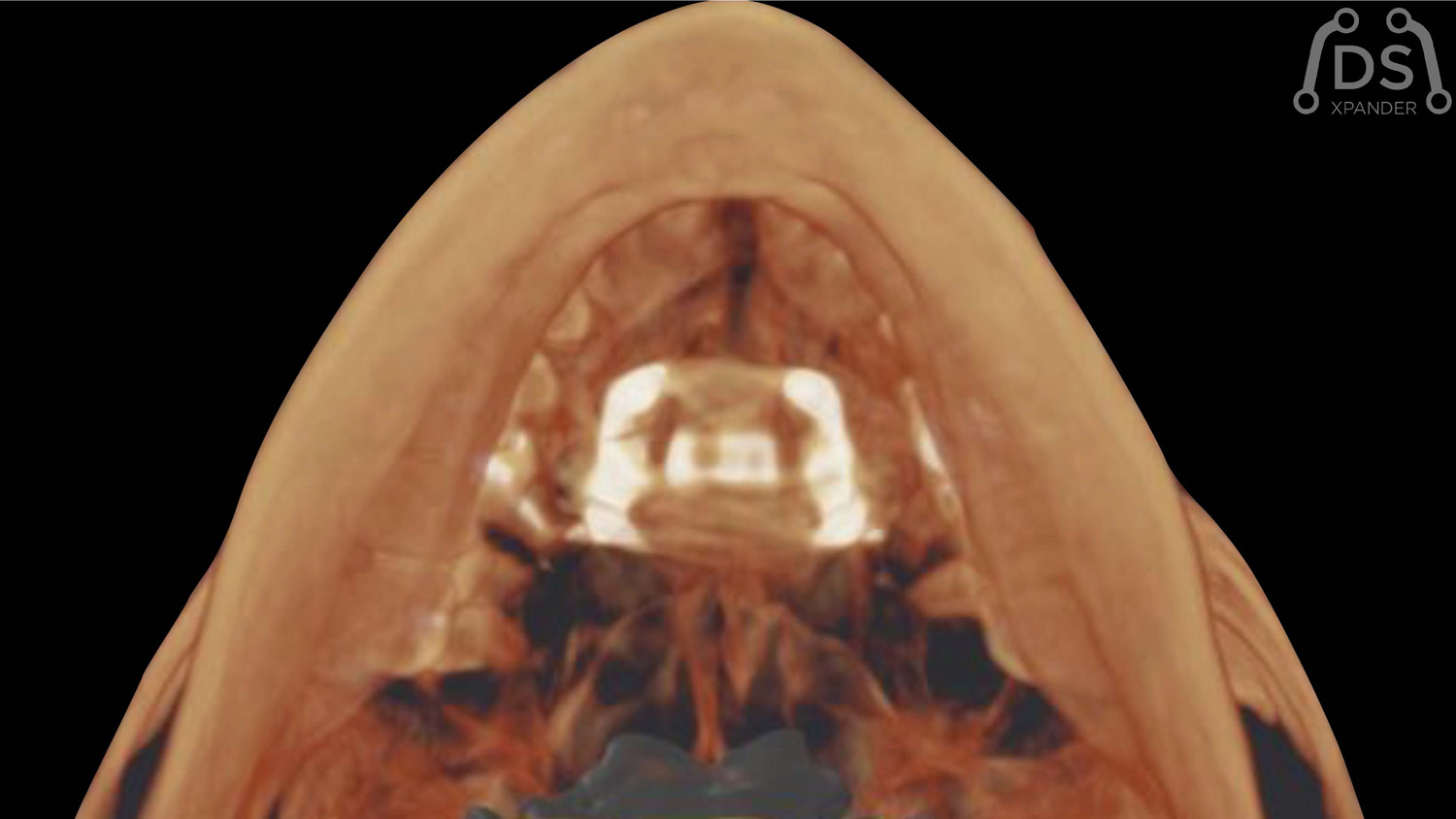
MARPE-BAME: Expansión palatina rápida
Dr. Armando Dias da Silva
Planificación 3D con imágenes DICOM de CBCT para Expansión BAME con tornillos de fijación no paralelos.
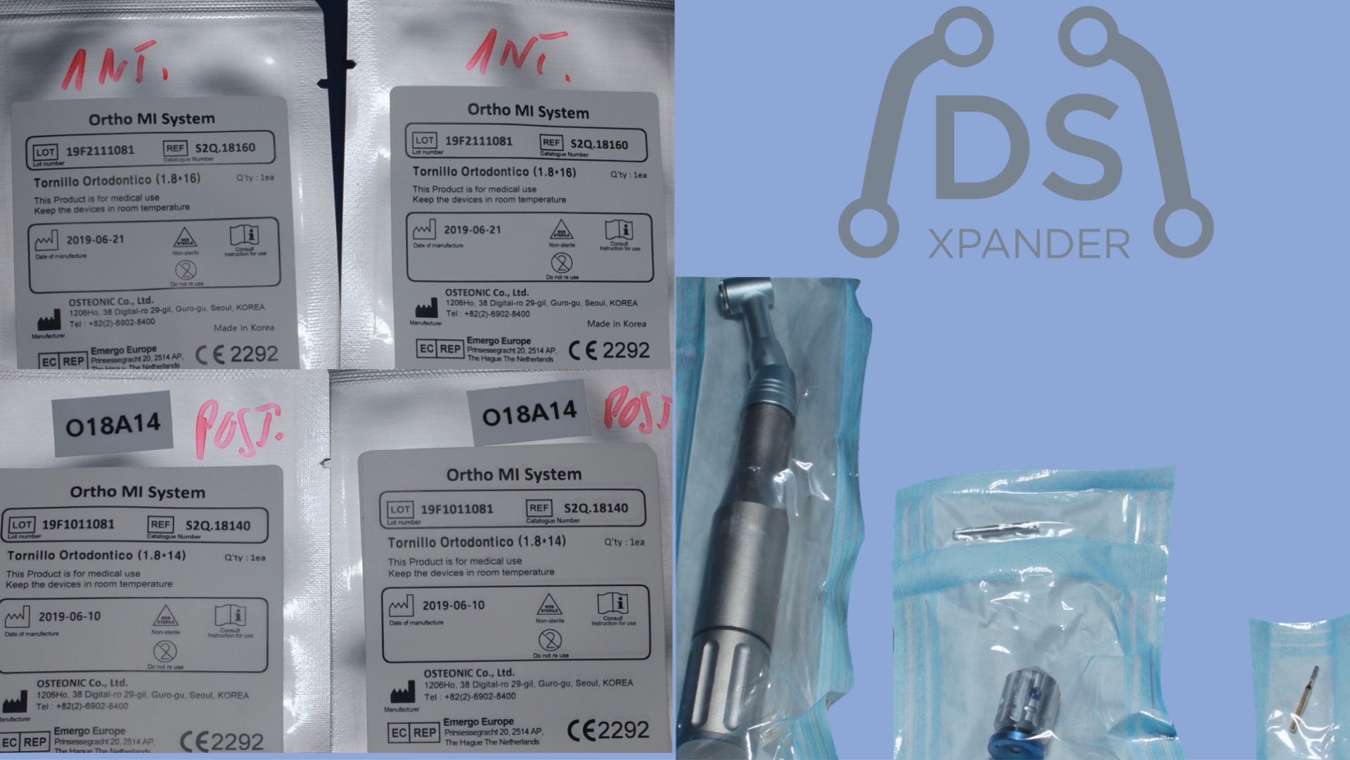
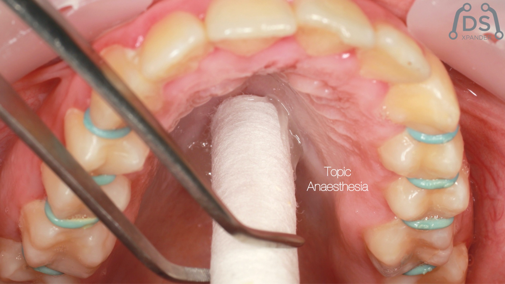
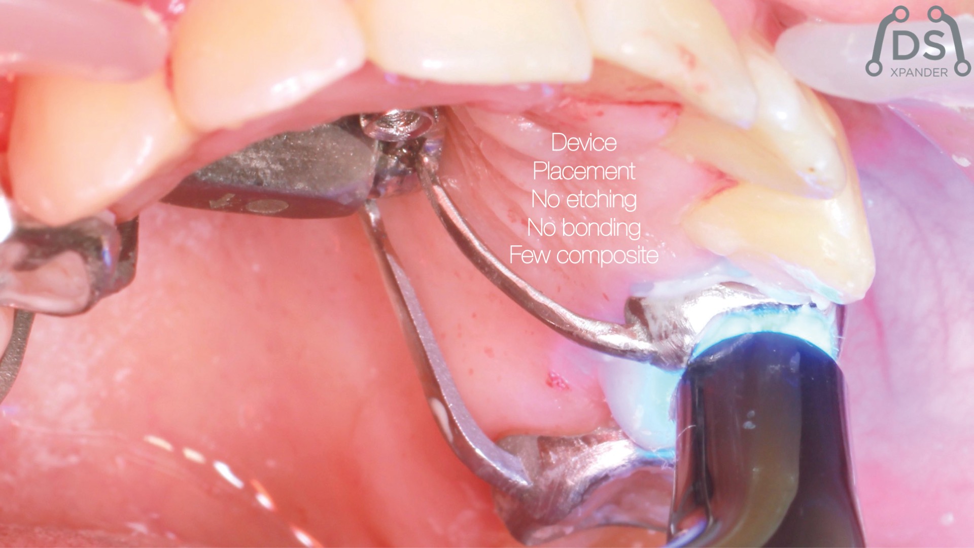
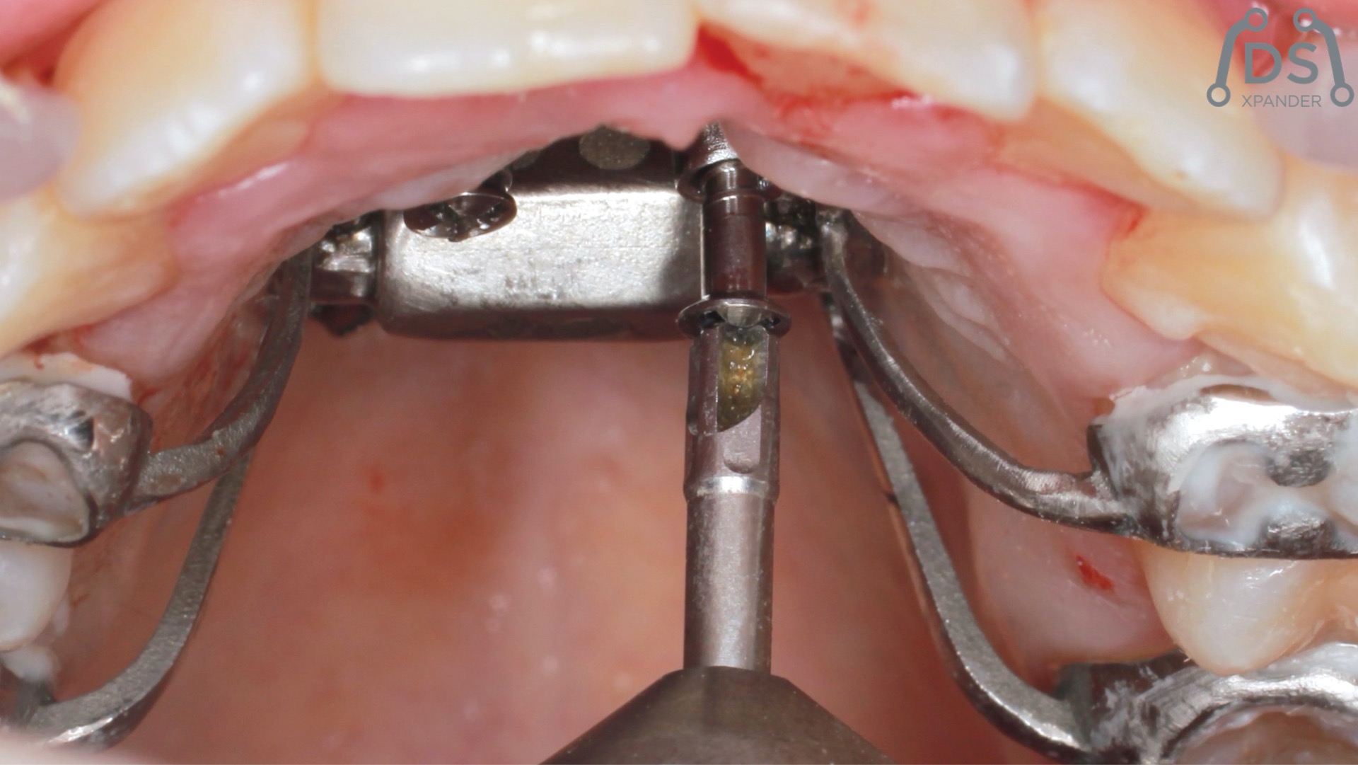
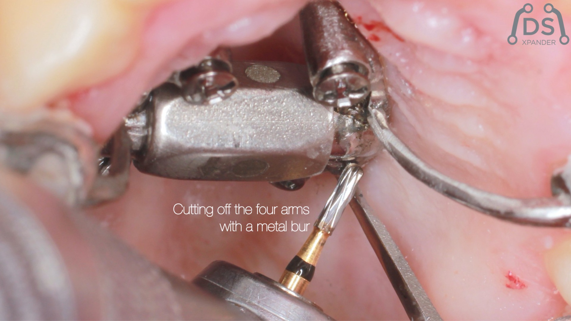
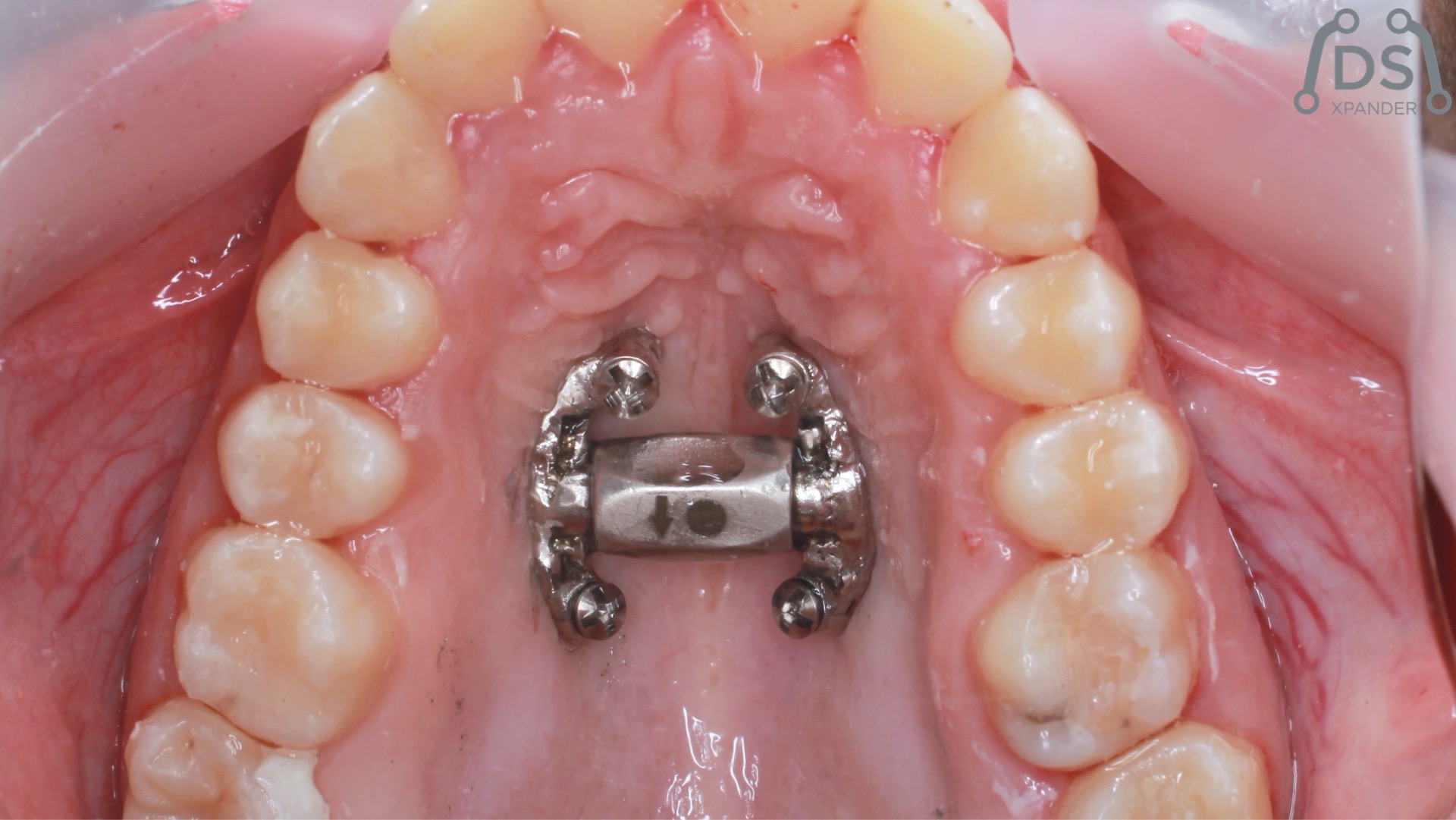
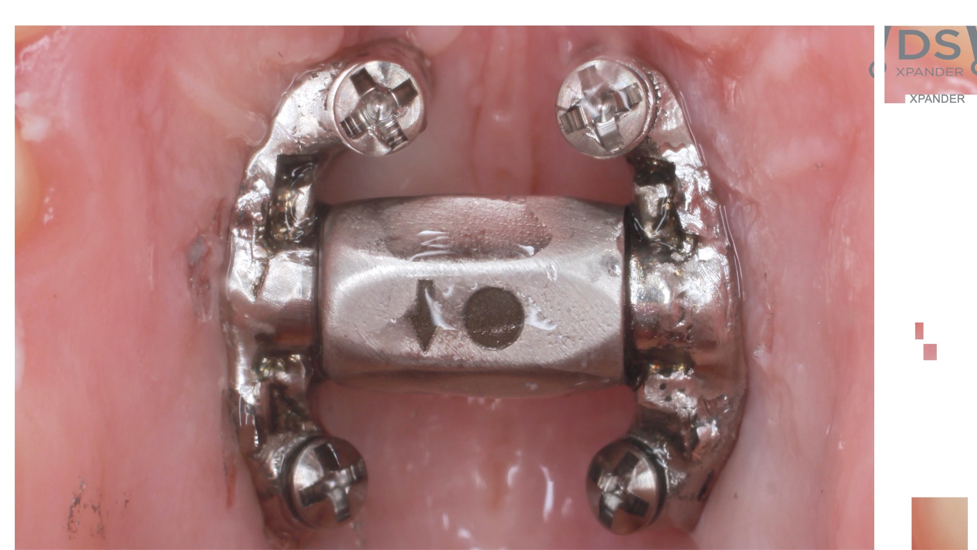
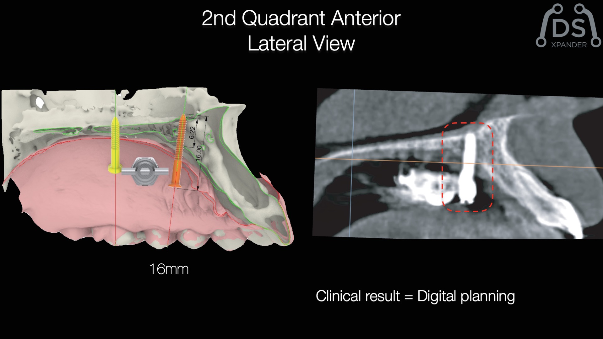
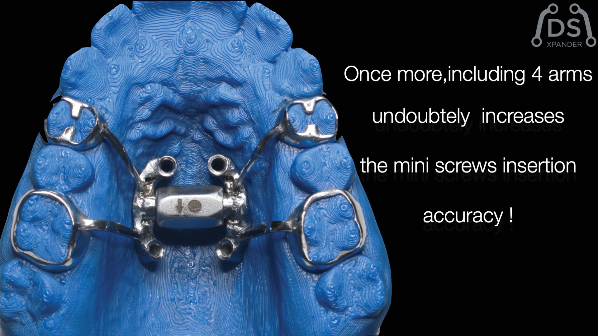
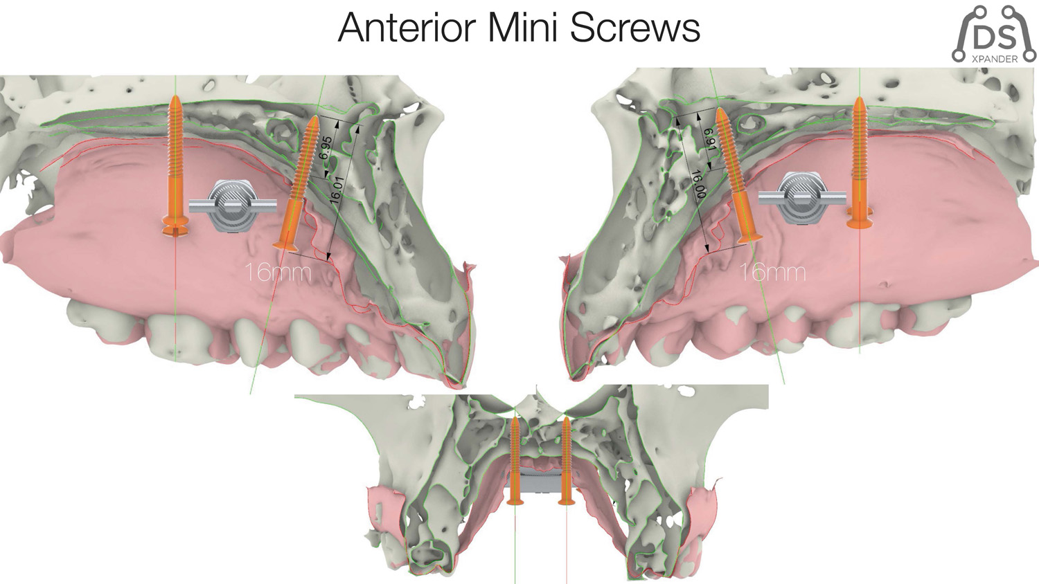
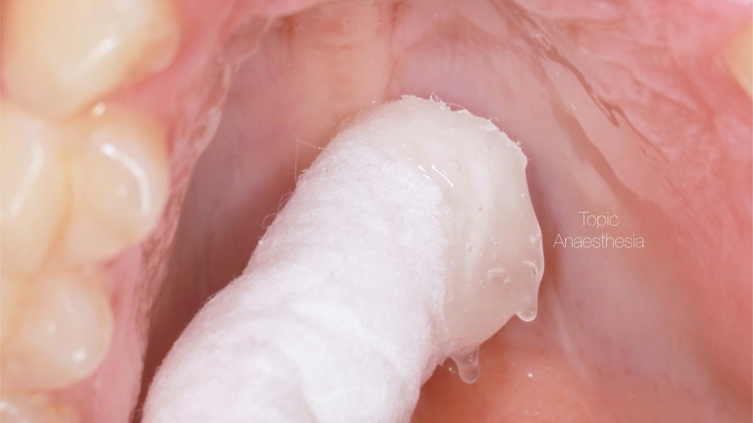
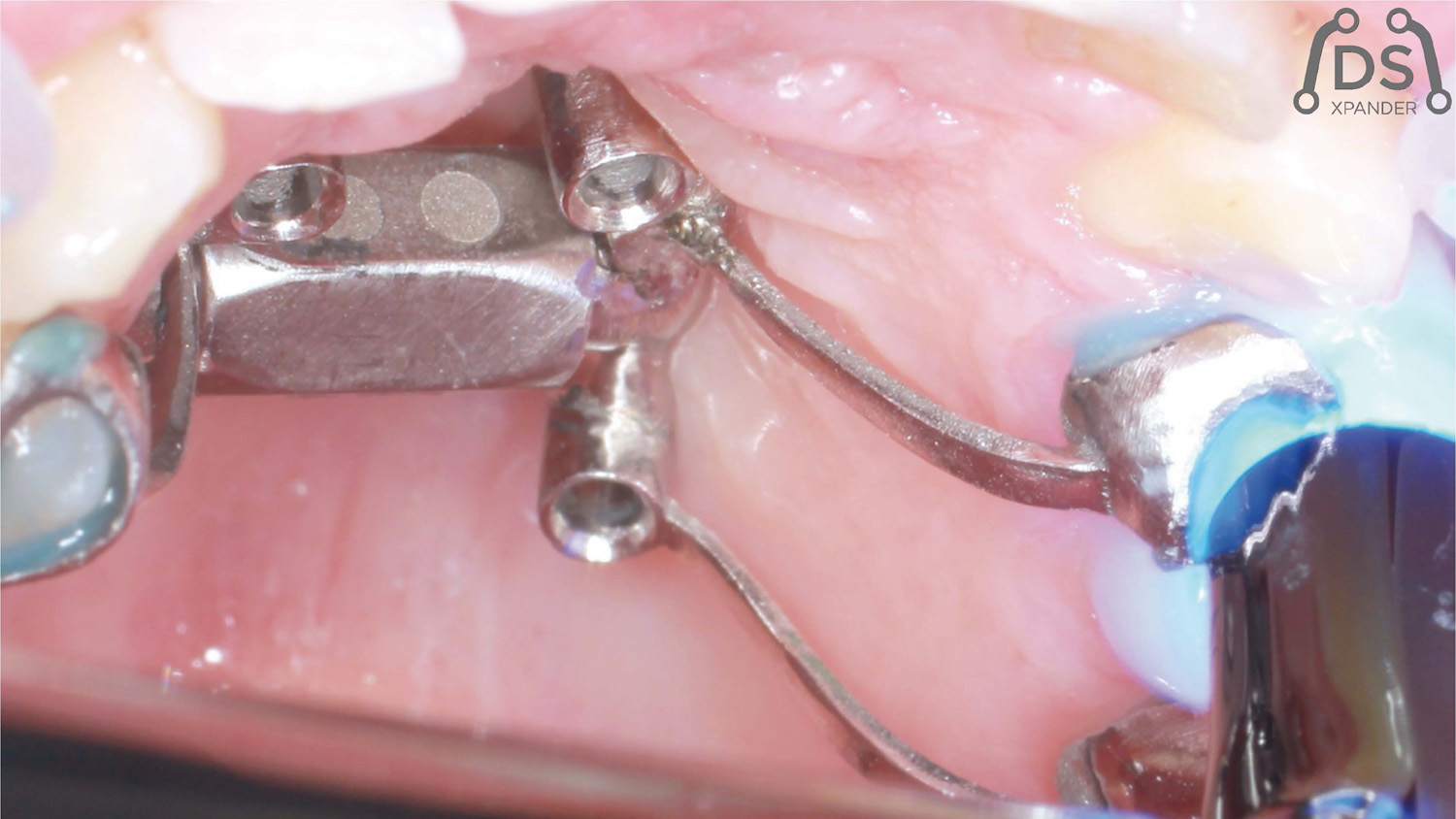
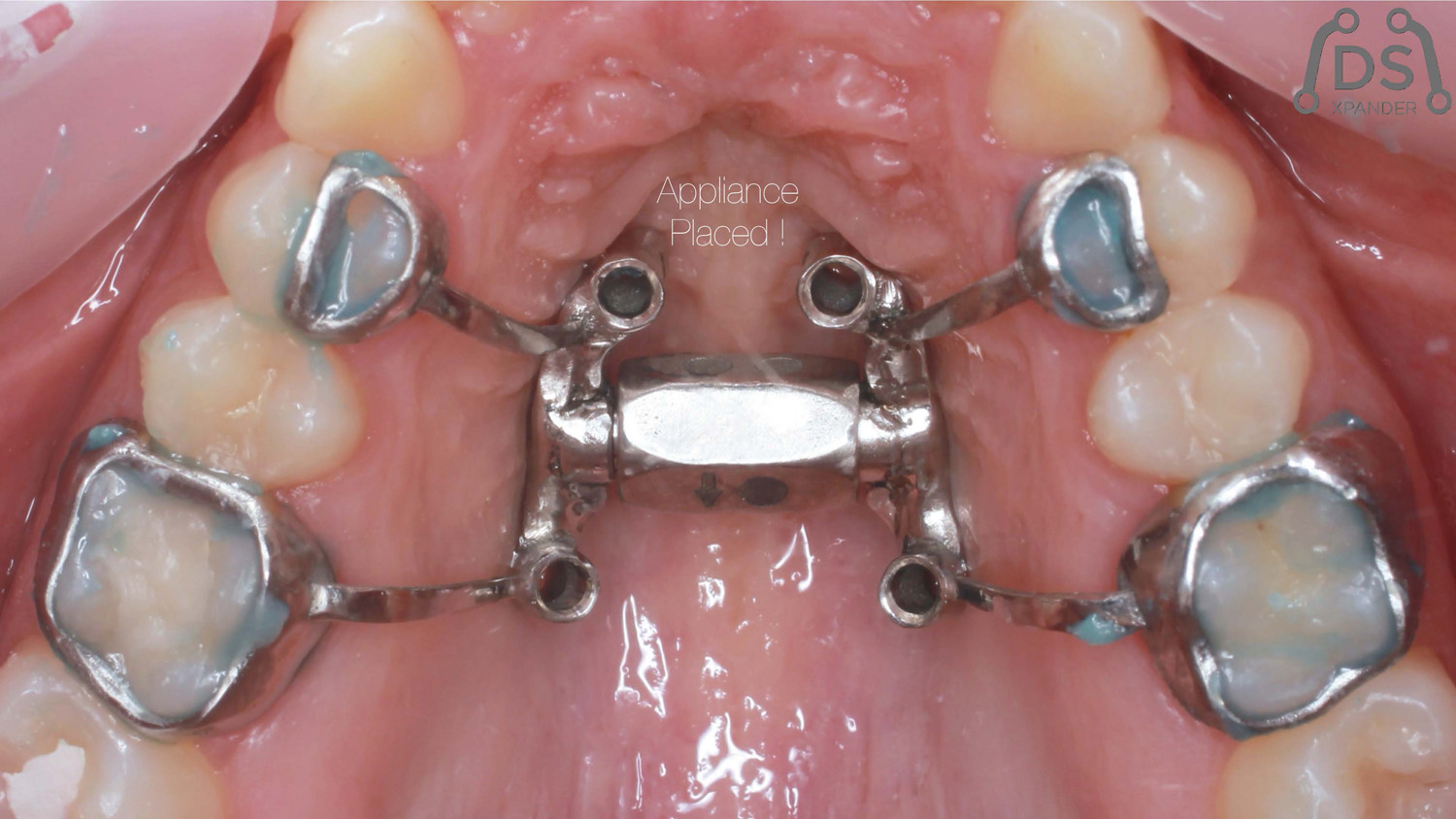
Paciente, mujer 25 años. Presentando una oclusión cruzada unilateral derecha por endognatia y endoalveolia, sin lateromandibula. Rigurosa planificación digital del caso con el software para CBCTfull3d Naicbu de MasorthodonciaDigital. La colocación de cuatro micro tornillos de 16mm de largo y activación del dispositivo DSxpander es muy sencilla se ha estado el procedimientos quirúrgico (SARPE). El plan transversal siempre es la priorida, el DSxpander ofrece una predictibilidad excelente.


Magnetic Mallet Dr. Fernando Gómez-Ferrer (Videos)
Videos cortesía de Dr. Fernando Gómez-Ferrer
Magnetic Mallet - Split Cresta Mandibular
Magnetic Mallet - Extracción de un cordal inferior izquierdo
Magnetic Mallet - Expansión Maxilar
Magnetic Mallet - Extracción de un molar Anquilosado y Fisurado
Magnetic Mallet - Atraumatic Dental Extraction
Magnetic Mallet - Split Cresta Maxilar
Magnetic Mallet - Extracción de Molares Inferiores podridos
Magnetic Mallet - Several Extractions
Magnetic Mallet - Extracción de Muela Anquilosada

SCOI. VII International Congress. Madrid. 24-26 Noviembre 2022.

VII Congreso Internacional de SCOI
Fecha: 24 al 26 de Noviembre de 2022
Lugar: Palacio Neptuno
Calle Cervantes 42
28014 Madrid
Visítanos!
Stand #14

Use Of Dynamic Navigation For Dental Implant Surgery
Dr. Jan D’Haese Ghent University, March 2015
Use Of Dynamic Navigation For Dental Implant Surgery
INTRODUCTION
Although osseo-integration of dental implants is predictable1, thorough pre-operative planning is a prerequisite for a successful treatment outcome.2Anatomic limitations as well as prosthetic considerations encourage the surgeon to obtain a very precise positioning of the implants. Historically, standard radiographic imaging techniques (intra-oral and panoramic) were available for investigation of potential implant sites. Throughout the years, spiral tomography and computed tomography (CT) were often used as a diagnostic tool.3 These techniques provide a 2-dimensional cross section image of the desired implant location and enables a detailed bucco-lingual view of the dimensions of the jawbone. Nowadays, it is well known that 3-dimensional CT scan based pictures allow a more reliable treatment planning than when only 2-dimensional data are available.4 Transforming the CT scan images into a 3D virtual image can be achieved using computer software packages,5 allowing for a 3D viewing using Computer Aided Design (CAD) technology. For years, stereolithographic guided surgery seemed to be the golden standard in computer guided implant surgery. The technique has been well developed over the last years and several scientific reports have been published regarding accuracy, complications, survival and success6. Real-time navigation seems to be a valuable alternative to stereolithographic (static) guided surgery as it offers the clinician some advantages compared to the former technique. Using real-time (dynamic) navigation one can avoid the fabrication of a stereolithographic template resulting in a less expensive treatment. As navigation is considered as a dynamic guided surgery system, changes to the treatment planning (location and size of the implants, number of the implants, flap or flapless…) can be easily made intra-operatively.
CASE PRESENTATIONS
The first patient treated was a 59 year-old female consulting the dental office for replacement of two premolars in the maxilla, in locations 15 and 24 (Fig. 1, Fig. 2, Fig. 3). Patient was in good general condition and was a nonsmoker. Intraoral examination revealed numerous amalgam fillings and some metal-porcelain crowns (Fig. 4). Teeth 15 and 24 had to be extracted previously due to cariogenic process. Periodontal screening showed no signs of pathology. Treatment involved placement of 2 osseo-integrated implants in the edentulous regions of the maxilla.
The second patient was a 55 year-old male visiting the office to restore a recently extracted lateral incisor (Fig. 5, Fig. 6). He was a non-smoker, in good general health and not suffering from any systemic disease. Intra-oral examination showed several crowns in the maxilla and a residual root fragment in location 15 (Fig. 7, Fig. 8). Patient suffered from moderate periodontal breakdown. This periodontal condition has been present yet stable for several years.
For both of the patients, impressions of the dental arch were taken prior to implant installation using an irreversible hydrocolloid (Cavex CA37, fast set, Cavex Holland BV, Haarlem, The Netherlands) to fabricate a diagnostic cast (Fig. 9). This cast was used as a model for the molding of theNaviStent in order to have a perfect fit. The NaviStent serves as scanning template and is worn by the patient during the scanning procedure and the surgery. (Fig. 10).
Afterwards, the patient was sent to the CBCT and a scan was made with the NaviStent in place.


PLANNING PROCEDURE
A standard CBCT scan was performed according to the procedure outlined in the scanning protocol by Navident (Navident, Toronto, Canada).
The CBCT images were converted into a DICOM image (digital imaging and communications in medicine) and transformed into a 3-D virtual model using the Navident software system. The clinician who placed the virtual implants in the resulting 3-dimensional model also performed the actual surgeries. The potential locations for implant placement, and corresponding implant lengths and widths were planned in a prosthetically driven way. A distance of at least 3 mm from the neck of implant to the gingival zenith was applied, allowing the biological width to create a connective tissue contour around the abutments.
SURGICAL PROCEDURE
The surgery was performed under local-regional anaesthesia. Appropriate aseptic and sterile conditions prevented post-operative infections. During the operation, the NaviStent was placed over the remaining teeth (Fig. 11). The NaviStent was primarily fixated around the undercuts of the remaining teeth and additionally by application of a denture adhesive (prothese kleefcreme).
The osteotomies were prepared at maximum of 1500 rpm using the Navident navigation system to guide the drilling procedure in real-time by indicating the desired drilling pathway on the computer screen. Prior to the use of each new drill, a calibration process is performed (Fig. 12). No punching of the gingival tissues was performed prior to the preparation of the implant sites.
In the first patient, 2 Xpeed® Anyridge® implants (Megagen, Seoul, South-Korea) were installed. At locus 15; a 10 mm length and a 4 mm wide fixture was inserted whereas at locus 24 a 13 mm length and a 3,5 mm diameter wide implant was installed (Fig. 13, Fig. 14, Fig. 15).
In the second patient, a solitaire Xpeed® Anyridge® implant with a length of 10 mm and a diameter of 3,5 mm was placed at locus 22 (Fig. 16, Fig. 17). An Xpeed® Anyridge® implant consists of a nanolayer of calcium ions incorporated on the sandblasted, large-grit, acid-etched (SLA) implant surface. All the implants were inserted into the maxilla with a maximum insertion torque of 35 Ncm.
As the implant fixtures were also calibrated for use with the navigation system (Fig. 18), their exact position could also be tracked during insertion. This means that both implant preparation drilling and the implant placement process are tracked in real time. Depth of drilling and placement are guided by Navident using on screen visual representation and auditory cues to aid the clinician. Immediately after implantation, cover screws were placed onto the implants and hand torqued (Fig. 19, Fig. 20).
Postoperatively, patient received a prescription for antibiotics (amoxicilline 1000 mg, 2x/d, 4 days), for non-steroidal anti-inflammatory drugs (ibuprofen 600mg, 3x/d) and for a mouthwash (chlorhexidine 0,12%, 2x/d). After 1 week, a post-operative visit was scheduled. No signs of infection or inflammation were present as the healing went on uneventfully (Fig. 21, Fig. 22, Fig. 23).
CONCLUSIONS
In a one week postoperative follow up the patients reported no pain or swelling associated with the dental implant procedure. Further postoperative results are being tracked and reported as part of a qualitative study being done in cooperation with the University of Ghent. The potential of the Navident dynamic navigation system with regard to minimally invasive and accurate implant surgeries will be evaluated during this study.


REFERENCES
1. Albrektsson T, Dahl E, Enbom L, et al. Osseointegrated oral implants. A Swedish multicenter study of 8139 consecutively inserted Nobelpharma implants. J Periodontol 1988; 59:287–296.
2. Jacobs R, Adriansens A, Naert I, Quirynen M, Hermans R, van Steenberghe D. Predictability of reformatted computed tomography for preoperative planning of endosseous implants. Dentomaxillofacial Radiology 1999; 28,37–41.
3. Rothman SL, Chaftez N, Rhodes ML, Schwarz MS. CT in the preoperative assessment of the mandible and maxilla for endosseous implant surgery. Work in progress. Radiology 1988; 168:171–175.
4. Jacobs, R., Adriansens, A., Verstreken, K., Suetens, P. & van Steenberghe, D. Predictability of a three-dimensional planning system for oral implant surgery. Dentomaxillofacial Radiology 1999; 28:105–111.
5. Israelson H, Plemons JM, Watkins P, Sory C. Barium-coated surgical stents and computer- assisted tomography in the preoperative assessment of dental implant patients. Int J Periodontics Restorative Dent 1992; 12:52–61.
6. D’haese J, Van De Velde T, Komiyama A, Hultin M, De Bruyn H. Accuracy and Complications Using Computer-Designed Stereolithographic Surgical Guides for Oral Rehabilitation by Means of Dental Implants: A Review of the Literature Clin Impl Dent Rel Res 2012; 14: 321–335
Navident is cleared by the FDA for sale in the United States. Navident is approved for commercial sales and distribution in Canada by Health Canada. It has also received the CE mark; please contact ClaroNav.
Input the main text content for your module here.

Dynamic Navigation In Fully Edentolous Maxilla
Dr. Hakan Uysal & Dr. Noyan Basal (Turkey 2017)
Dynamic Navigation In Fully Edentoolous Maxilla
Introduction
Preoperative planning is the most important part of a successful implant rehabilitation and requires multiple parameters to be considered for the precise placement of implants. The implants should be placed not only within anatomical boundaries but also be strategically located to support a prosthesis that will fulfil both functional and aesthetic requirements.
3-D virtual images are being used through computer software, which transforms CBCT scans into 3-D virtual models. However, after a precise planning or virtual realisation of the treatment, the osteotomy should also be executed precisely according to the plan and would likely require guidance of the drills and the implant.
For years, stereolithographic static guides have been used successfully for implant osteotomies, using detailed information implemented through 3-D virtual images.1,2 Static guides on the other hand present several disadvantages. The loss of tactile feeling during osteotomy and the fact of being limited to the predesigned drilling trajectory are considered to be their major drawbacks.
Real-time navigation
A recent technology, which provides dynamic guidance through a real-time navigation for implant osteotomy, offers not only accuracy, but also additional valuable advantages during an operation.3,4 With this technology, the location and diameter of implants can be modified and a flap can be incised intraoperatively whenever
needed.
Furthermore, dynamic navigation enables the surgeon to adjust the surgical plan during surgery. In case of an unexpected low bone quality, an additional implant could be planned with the software and placed additionally. Moreover, one of the most significant benefits of dynamic navigation is the ability to use it also for alveoloplasty and reshape the alveolar crest’s topography during the same surgery, together with the implant placement.
The precise location of implants is case-specific and determined by different factors. If an edentulous case is to be restored with an implant-supported screw-retained fixed prosthesis, implant locations should be critically examined whether they can provide screw access holes within occlusal or palatal/ lingual parts of the restoration. Frequently, alveoloplasty is required for the recontouring of the ridge in order to obtain sufficient bone thickness at the level of the implant’s collar. /
This crestal trimming of bone may also be necessary in order to increase the inter-arch space and provide a sufficient volume for the restorative material, since dentogingival prostheses are frequently required to enhance aesthetics. In such cases, dynamic guidance can be used to level the alveolar crests as planned on virtual images, followed by precise multiple osteotomies.
Case
The following case report describes the treatment of a 65-year-old male with an one-year history of maxillary partial edentulism (Fig. 1). He was discontent with the stability of his prosthesis and expressed that through the unstable prosthesis situation he has lost social self-confidence. In the initial appointment he thus stresses his need for a “fixed solution”.
His medical history did not reveal any specific systemic disease or condition that contraindicates oral surgery. The patient’s soft tissues on the edentulous ridges were healthy and panoramic X-rays showed expanded sinuses at both sides and irregular alveolar ridges. The treatment plan, carried out for a maxillary screw-retained fixed prosthesis, included two implants at the pre-maxillary region and two tilted in the posterior maxilla to avoid a sinus lift surgery.
Stent placement
In order to acquire both anatomical and prosthetic information prior to the surgery, a scan prosthesis was manufactured by duplicating the maxillary denture (Fig. 2). It is important that the scan prosthesis has the same aesthetic and functional information as the complete denture or set-up. Thus, the scan prosthesis was checked for its fit, aesthetics and maxilla mandibular relation (Fig. 3). The scan prosthesis was then used together with a Navident Edentulous Kit for CBCT imaging.
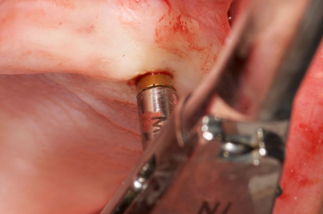
The Navident edentulous protocol consists of a SDI (Small Diameter Implant of 2.2mm or 2.5mm diameter), which is inserted into the alveolar ridge of the arch to be operated, prior to the acquisition of the CT scan. This temporary SDI serves as a mount for the CT marker and for the Jaw Tag used for the registration of the CT scan to the patient and for tracking the patient’s jaw during surgery.
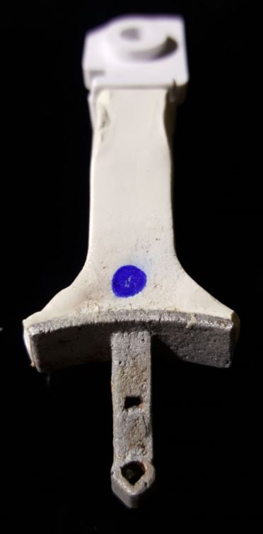
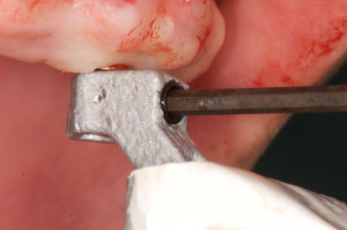
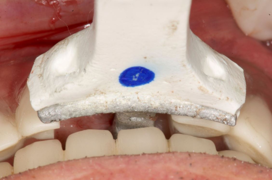
The SDI can be placed either in a vertical position or in a horizontal position in relation to the alveolar crest. A special plastic arm with a proprietary aluminium bracket is then used for the connection of the CT marker and Jaw Tag to the SDI. Two types of arms are available: one for a vertically placed and another for a horizontally placed SDI (Figs. 4a and b). In the presented case, the SDI has been placed vertically to achieve the required stability (Fig. 5).
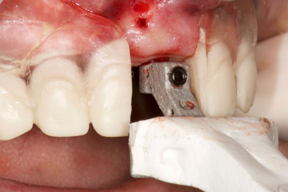
The CT marker, containing the fiducial marker used for the registration of the CT scan to the patient, was attached to the V-type arm on the fix-plate at one end. At the other end, the assembly was placed over the SDI’s square head and secured to it using a setscrew which was embedded in the aluminium bracket, with this creating a complete “NaviStent” (Fig. 6).
The scan prosthesis was then modified to accommodate the aluminium bracket before it was placed over the maxillary edentulous ridge (Figs. 7 & 8). For accuracy purpose, it is imperative that the scan prosthesis is stable, while at the same time it should not interfere with the NaviStent.
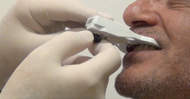
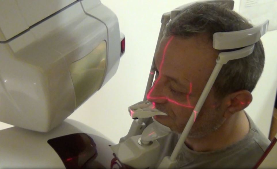
CT scan
The following CBCT imaging protocol for Navident dynamic navigation was applied during CT imaging. Before the scanning procedures, both the modified scanning prosthesis and the NaviStent had been placed into the patient’s upper jaw (Figs. 9 & 10). A CT marker was then connected to the NaviStent. A scout view had been acquired prior to the actual scan to verify the presence of the CT marker in the CT scan. In order to allow for accurate registration, at least three corners of the fiducial marker must be present in the scan. In order to maintain a high level of accuracy during navigation, it is mandatory that the slice thickness must not exceed a maximum of 0.4mm. In this case, the slice thickness had been set to 0.3mm. Afterwards, the scan was exported in DICOM format, then imported into Navident.
Osteotomy planning
When the CT scan is imported into Navident, a proprietary algorithm detects the fiducial’s image in the scan, then registers it with a mathematical model of the fiducial that is stored in the computer memory. This enables Navident to map the Jaw Tag, which is the tag mounted onto the patient, to the CT image during navigation.
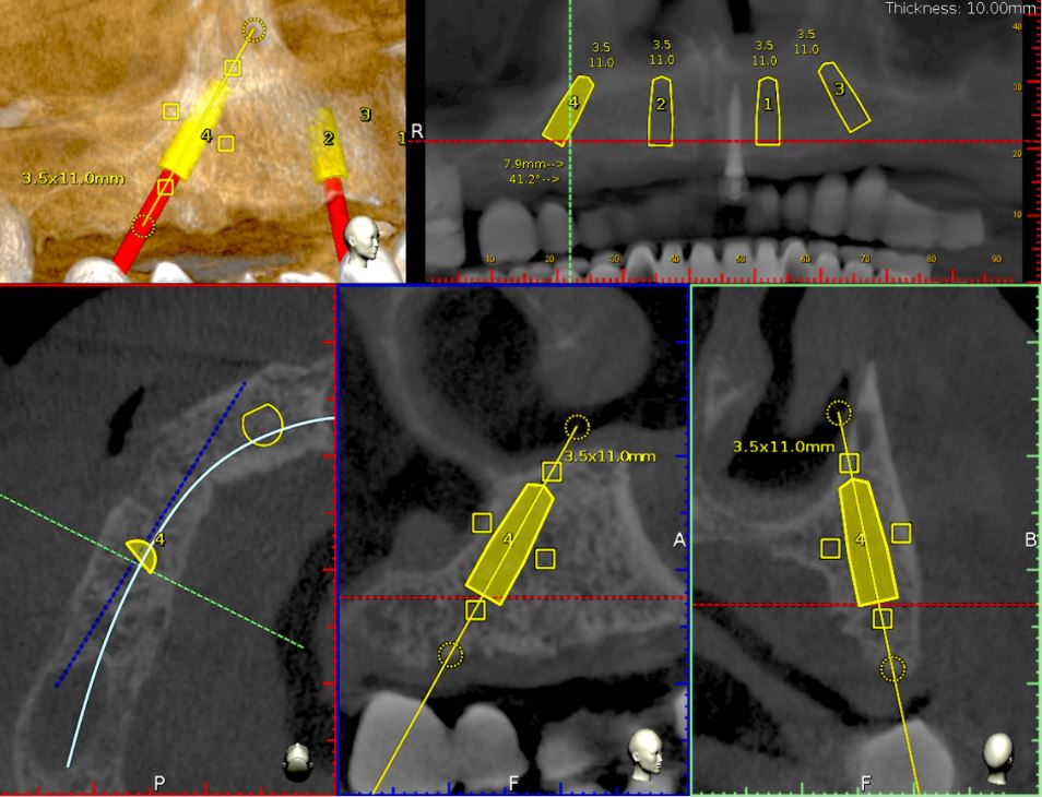
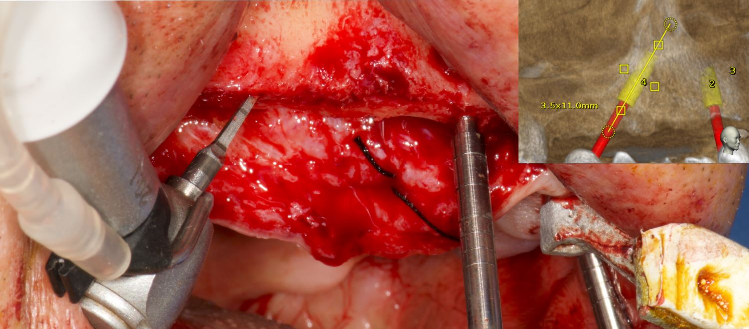
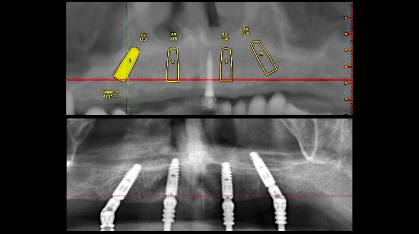
For this case, Ankylos dental implants had been selected. The implants with a diameter of 3.5mm and a length of 11mm were planned on the locations 15, 12, 22 and 25 using the Navident planning software (Fig. 11). The following parameters were considered when osteotomies were planned:
- Alveolar ridges, though they had a sufficient bone height, were narrowing at the crestal 1/3. Without waiving or compromising the restorative information, the implant locations were planned to be deeper where at least 2mm of buccal plate thickness could be achieved.
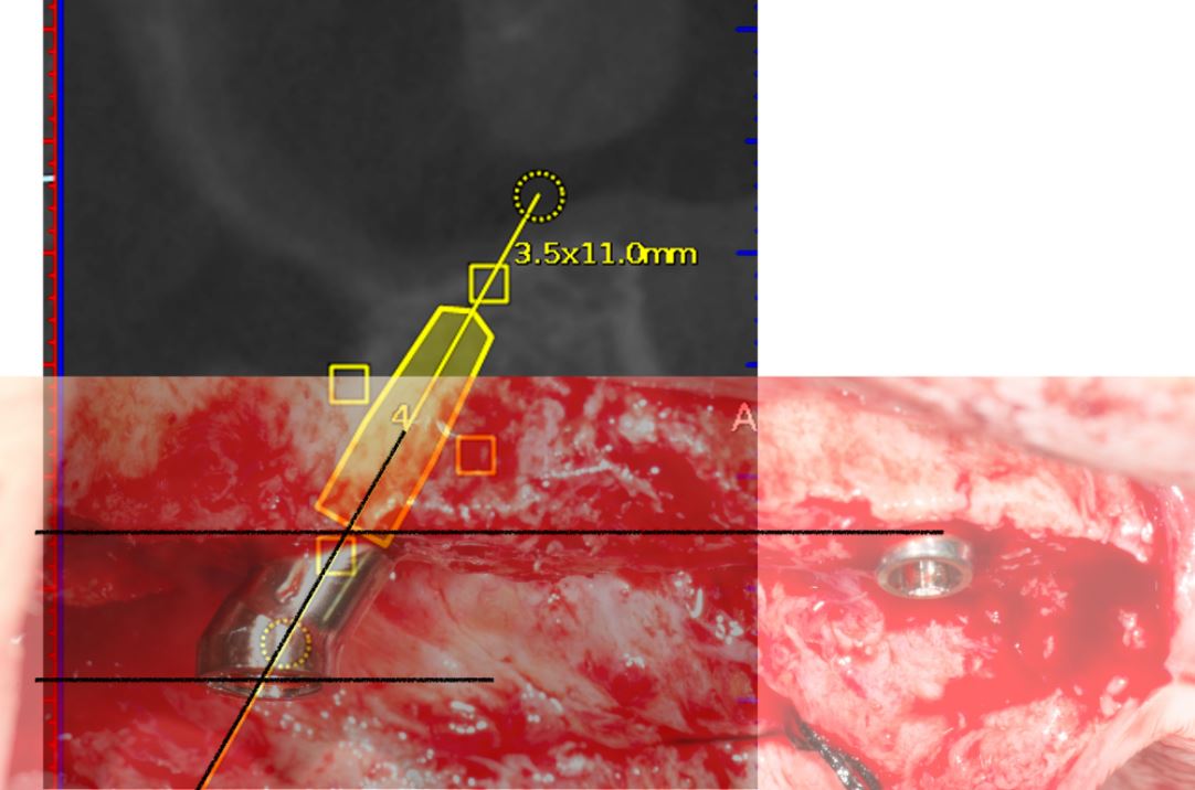
- Straight implants were placed at 12 and 22 and tilted ones at 15 and 25.
- Angulated distal implants were planned 1mm mesially to the sinus wall.
- The angle of distal abutments was planned to be 30 degrees to the occlusal plane to have the retaining screws access holes placed in the denture’s occlusal aspect since screw-retained abutments have 30-degree joints.
- The plane of the implant collars was planned to be parallel to the occlusal plane.
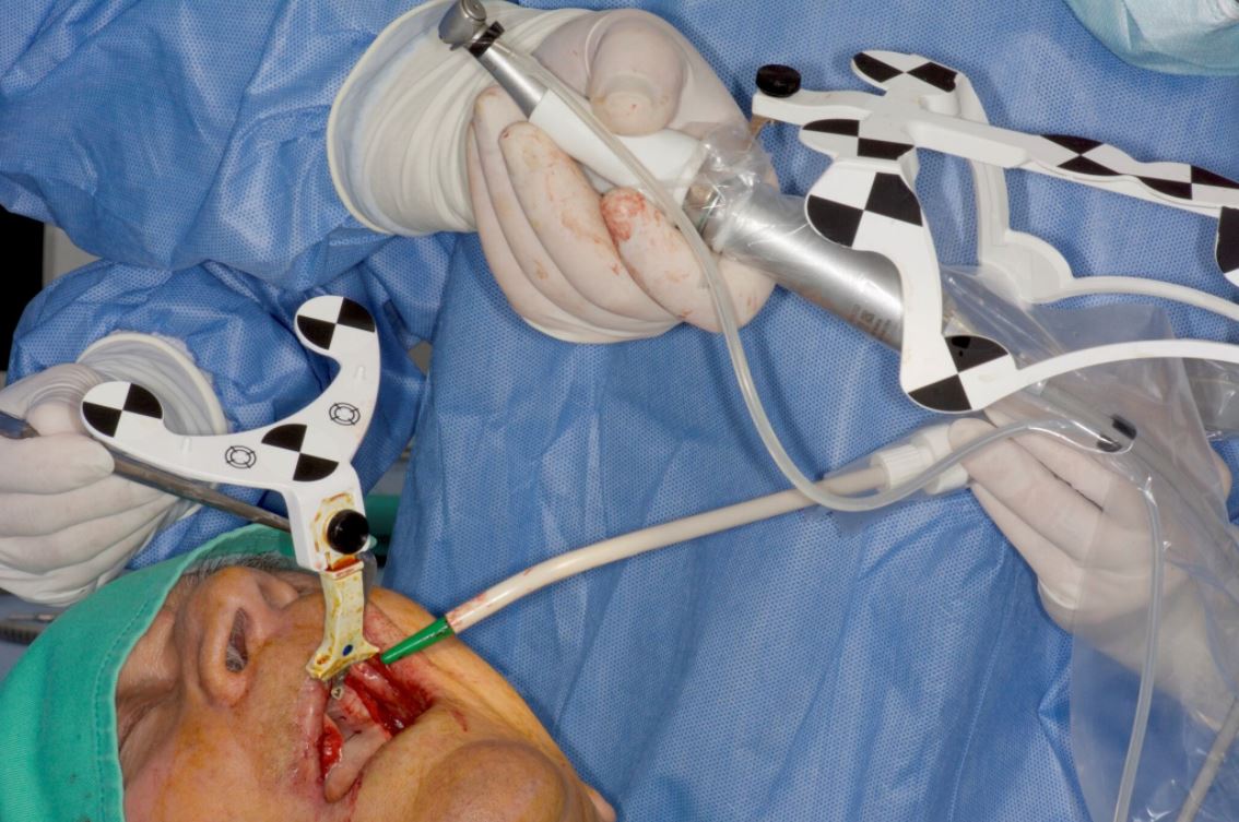


Surgery
Before surgery, the CT marker was disconnected from the NaviStent Arm and replaced by the Jaw Tag, which is detected by the Navident camera. A Drill Tag was installed onto the handpiece (Fig. 12). Together with the Jaw Tag, they provide real-time feedback during surgery, enable the surgeon to communicate with the software and place the implant as planned.
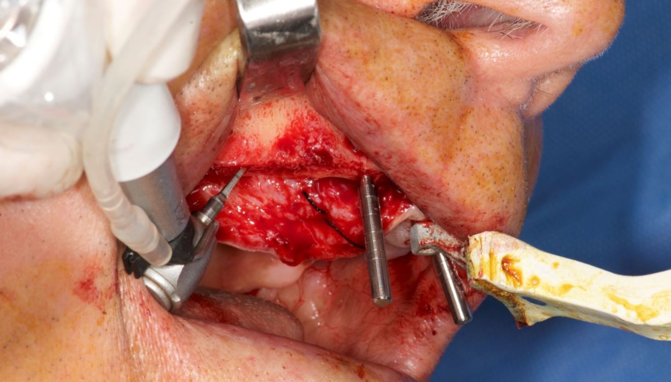
A crestal incision was made at either side. Pilot drills were used to start osteotomy followed by the Ankylos Dental Implant Drilling protocol. All drills were navigated according to the planned trajectory, until realtime feedback confirmed that its tip has reached the apical end of the planned osteotomy. The alveolar crests were levelled by a rongeur (Fig. 13). Between each trimming attempt, the pilot drill was touched to the trimmed surface of the crestal bone and its level was checked on the virtual image.
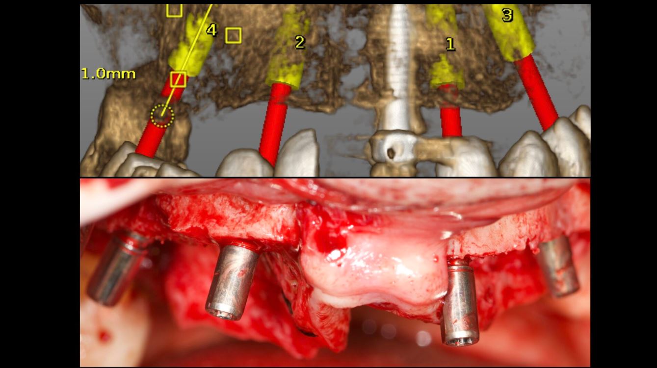
The trimming of the bone was completed under the guidance of dynamic navigation and the pilot drill was again touched to the newly formed alveolar crest. Implants were inserted in the osteotomies as planned, the gingival tissue placed back and sutured with coated poly-glactin 910 sutures. The patient was medicated with antibiotics and chlorhexidine mouth rinse and was released with NSAID’s (Figs. 14–16).
Conclusion
The Navident navigation surgery system achieves a successful guidance both in alveoloplasty and implant osteotomies in the edentulous maxilla (Figs. 17–19). In the presented case, the proposed protocol was highly efficient in gathering 3-D prosthetic and anatomical information for the planning. Dynamic navigation provided a precise guidance in the execution of the planned osteotomies through a flexible surgical operation.
References
1. D’haese J, Van De Velde T, Komiyama A, Hultin M, De Bruyn H. Accuracy and Complications Using Computer-Designed Stereo-lithographic Surgical Guides for Oral Rehabilitation by Means of Dental Implants: A Review of the Literature Clin Impl Dent Rel Res 2012; 14: 321–335.
2. Laleman I, Bernard L, Vercruyssen M, Jacobs R, Bornstein MM, Quirynen M. Guided Implant Surgery in the Edentulous Maxilla: A Systematic Review. Int J Oral Maxillofac Implants. 2016; 31 Suppl: s103-17.
3. Somogyi-Ganss E, Holmes HI, Jokstad A. Accuracy of a novel prototype dynamic computer-assisted surgery system. Clin Oral Implants Res. 2015 Aug;26(8):882-90.
4. Jung RE, Schneider D, Ganeles J, Wismeijer D, Zwahlen M, Hämmerle CH, Tahmaseb A. Computer technology applications in surgical implant dentistry: a systematic review. Int J Oral Maxillofac Implants. 2009;24 Suppl:92-109. Review.
Contact
Prof. Dr Hakan Uysal
DDS, PhD, Prosthodontist
Abdi Ipekci Cad. 61 Tesvikiye
Istanbul, Turkey
Tel.: +90 212 219 6744
[email protected]
Dr Noyan Basal
Klinik212 dental clinic
Valikonagi str. No:86/a
Nisantasi
Istanbul, Turkey
Tel.: +90 5324139118
[email protected]

Flapless Implant Placement With Dynamic Navigation
Naheed Mohamed, DMD 2017
Flapless Implant Placement With An Internal Sinus Lift Using Dynamic Guided Navigation
INTRODUCTION
Today implant surgery is focused on being minimally invasive with an emphasis on prosthetically guided implant placement. Implants which are not placed in a prosthetically favorable position are at risk for future complications involving the prosthetic components or peri-implant tissues. Successful implant placement is not only judged by osseointegration but also the esthetics. In a climate where implant therapy is held to the highest of standards; using advanced tools to simplify surgical dental implant placement is a requisite for success.
Currently computer guided surgery involves the use of a CBCT (cone beam computer tomography) scan and possibly an intra-oral scan to allow personalized digital surgical planning. This plan is then transferred to the patient in the form of a surgical guides to aid in accurate implant placement. These guides however are static and do have some drawbacks. They are not always stable depending on whether they are supported by teeth, mucosa, or bone. Limited mouth opening does become an issue when surgical guides are used to place implants for posterior dentition. And lastly if there is any error in the digital planning, segmentation of the anatomy, or data transfer to the guide fabrication, the error is passed down onto the guide’s implant position. If errors are noted during surgery, then the guide becomes essentially useless.
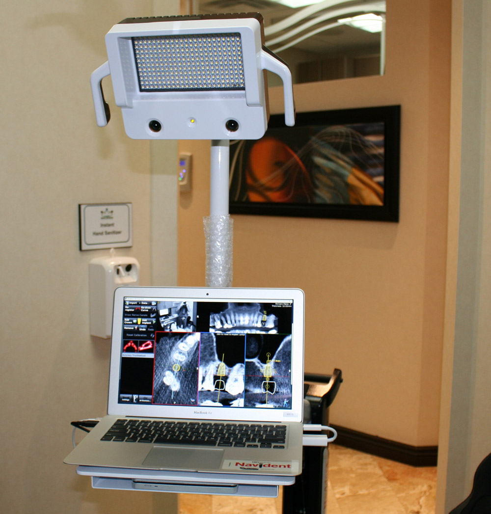
The next evolution in guided dental implant surgery comes from neurosurgery and orthopedic spine surgery where it has been used for quite some time. Claronav Inc has developed a live navigation system using optical tracking cameras (Fig 1) during implant surgery to provide the surgeon with CBCT based real-time three dimensional drill guidance during implant surgery. One of the main advantages of this Navident system (Fig1) is that dynamic navigation allows intra-operative changes to implant position in real time if any errors or anatomical complexities are noted during the surgery. The flexibility of having a guided implant placement in a digitally planned ideal location without the need for a static surgical stent and having the osteotomies live navigated on CBCT data using optical tracking is a game changer for implant dentistry. This open system also has the flexibility of using any implant system and any drill to guide placement. The case presented below showcases the flexibility of real time navigation where Straumann implant drills are used for placement of an implant with a simultaneous internal sinus lift using the Hiossen CAS-KIT drills with the Navident system.
Case Report
The patient was 57 year old healthy female that was referred to our clinic to replace the missing maxillary second premolar at the 2.5(13) site with a dental implant. The Navident workflow consists of four main sequential steps: stent fabrication, CT(computer tomography) scan with the stent and affixed CT marker in the patient’s mouth, digitally planning the implant surgery in the Navident software, and lastly completing the live guided implant surgery. One of the biggest advantages of the Navident system is that these four sequential steps can all be completed in one appointment provided the clinic has an available CBCT scanner.
The NaviStent functions as a retainer onto which the CT marker is affixed to while the patient undergoes her CBCT scan. The NaviStent is a custom single use retainer made of a thermoplastic material called Naviplast than can be heated in hot water and molded to the patient’s dentition. The stent was trimmed and the planned implant site was cut open to expose the ridge. The CT marker was then fixed to the stent by way of a thumb screw. The NaviStent with the attached CT Marker was placed into the patient’s mouth. The stent was checked for stability in the patient’s mouth. A CBCT scan was completed for the entire maxillary arch being sure to include the arm of the CT marker which contains the aluminum fiducial.
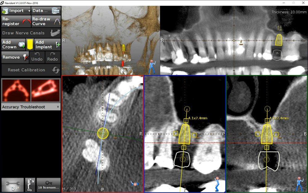
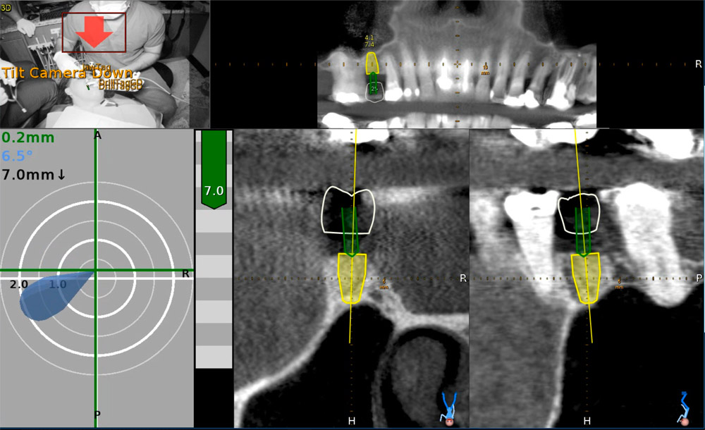
The CBCT scan was then imported into the Navident software. The Navident software automatically registers the fiducial and asks you to inspect the registration to ensure there is no malalignment. Our implant position is prosthetically determined, so our first step was to place a virtual crown at the 2.5 (13) site. The vertical height of bone from the ridge to the sinus floor was measured using the software measuring tool and found to be 7.4mm (Fig 2).
Our treatment plan involved placing a Straumann Bone Level Tapered SLActive Roxolid 4.1mm x 10mm implant as a single stage flapless approach with an internal sinus elevation. Taking advantage of the freedom of the Navident system, we were able to plan our surgery to place a Straumann dental implant and complete our internal sinus lift using the HIOSSEN CAS-KIT (Crestal Approach Sinus Kit). To control our drilling depth and use the live navigation to guide us to the sinus, a digital implant was placed in the ideal location with respect to the digital crown. This digital plan would guide us to the sinus floor for the sinus elevation and allow ideal implant placement.
Live Navigation Implant Surgery and Internal Sinus Elevation.
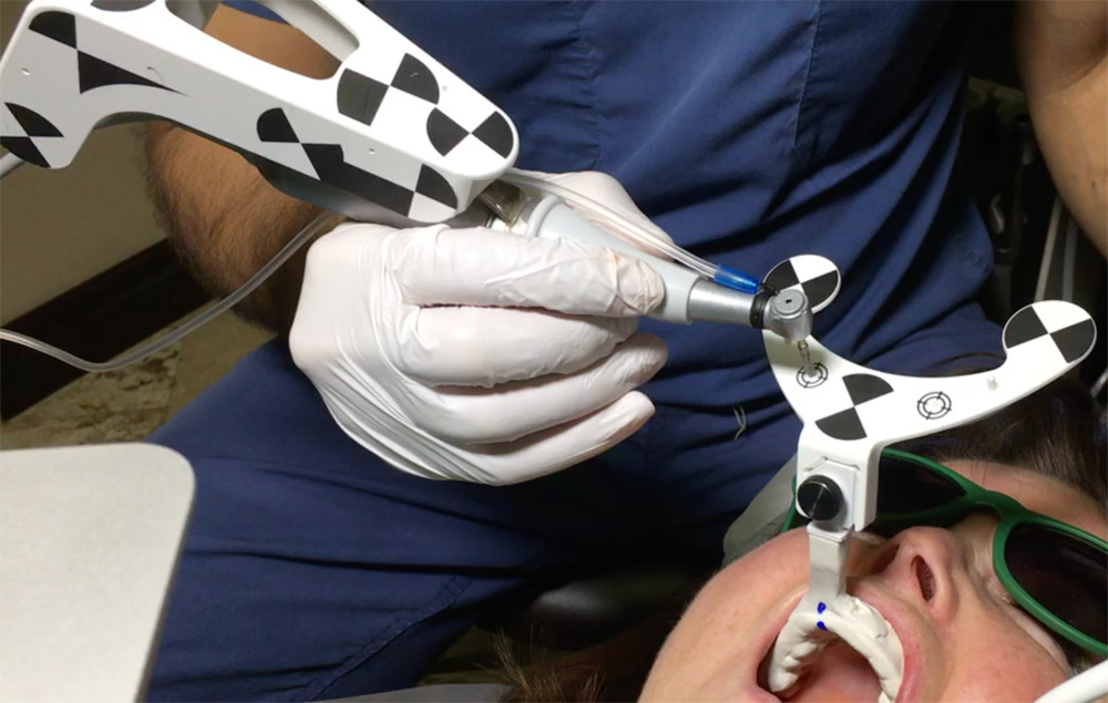
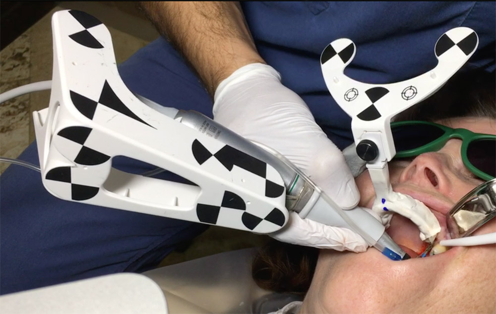
The patient was seated for the implant surgery. Local anesthetic was given. The single use JawTag was fixated to the NaviStent with the provided thumb screw. The tag adapter was mounted onto the surgical handpiece and fastened in place according to the company’s instructions. The single use DrillTag was attached to the tag adapter on the surgical handpiece. The NaviStent was placed into the patient’s mouth with the JawTag visible for the Navident camera to detect. Once the CT markers are visible by the camera, they become visible on the side panel on the monitor. The next step was to calibrate the drill axis by placing the handpiece head onto the calibration peg present on top of the JawTag. The handpiece was then rotated back and forth around the peg to register and calibrate the drill axis. The system then prompts us to calibrate the drill. The initial precision point drill was then placed onto the handpiece and calibrated by placing the drill tip into the dimple present at the center of the target on the JawTag (Fig 3). Once the drill tip was calibrated, it then became visible on the monitor against the CT image when it is placed into the surgical field. Our next step was to verify the drill tip position. This was done easily by placing the tip of the bur on a landmark in the jaw to verify accuracy of its positioning. In our case the tip of the drill was verified by placing it on the cusp tip of the neighboring tooth 2.4 (13). The drill was then brought to the surgical site (Fig 4) and the navigated drilling screen comes up which shows a Target view and cross sectional views of the CT images with the drill image visualized in its real-time position (Fig 5). The target and cross sectional views allow you to position the drill into the ideal digitally planned implant position based on the live view of the drill over the CT images.
The drilling process was started with a precision drill to punch a dimple into the bone and give us a soft tissue bleeding point. The bleeding point was then used as a marker to remove a 4mm diameter of crestal gingiva with a tissue punch. The Straumann pilot drill was then calibrated and verified on the handpiece. The 2.2 mm pilot drill was then used to drill at 800rpm to about 7mm into the osteotomy using the live navigation to guide us into the digitally planned position. The second 2.8mm drill in the Straumann Bone Level Tapered implant protocol was calibrated, verified and live navigated to the desired position at a depth of 7mm into the osteotomy.
The drills were now switched to the Hiossen CAS-KIT drills to allow removal of the cortical bone at the floor of the sinus without damaging the Schneiderian membrane. The CAS-Drill tip has an inverse conical shape that forms conical bone chip as it drills to allow it to safely elevate the sinus membrane without perforating it. The bone particles formed when drilling discharge upwards producing a membrane auto-lift function. The Hiossen CAS 3.3mm drill was used with an 8mm stopper as a back up to prevent us from forcefully pushing too deep into the sinus. The CAS drill was calibrated and verified and then live navigated to access the sinus membrane.
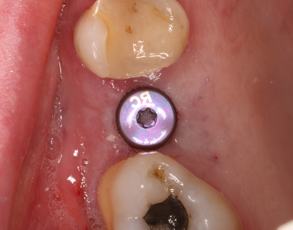
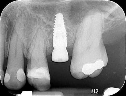
Once the membrane was exposed through the osteotomy, it was elevated using hydraulic pressure with the CAS-Kit Membrane Lifter and sterile saline. Cortical allograft chips were then gentled pushed into the void created from the membrane elevation. The jaw stent was removed and the implant was placed through the osteotomy with direct vision. The Straumann Bone Level Tapered 4.1mm x 10mm implant was placed with 50Ncm of primary stability. A healing abutment was then hand torqued in place (Fig 6). A post-operative peri-apical radiograph (Fig 7) was taken to assess the implant placement. The implant can also be live navigated into place, however it needs to be calibrated by touching the tip of the implant over the JawTag dimple, and due to the risk of contamination we chose to place it with direct vision. The company recommends placing a sterile piece of nylon over the dimple when calibrating the implant to keep the conditions of the implant sterile.
Due to the flapless live guided Navident protocol, we were able to release the patient, with no sutures required and minimal trauma to the site. The patient was prescribed anti-inflammatory analgesics and placed on a 7 day antiobiotic course. Her healing was uneventful with minimal discomfort to the area.
Conclusion
Computer guided placement of dental implants is significantly more accurate than free hand surgery. In areas of complex anatomy, computer guided navigational surgery is superior to conventional implant surgery when it comes to preventing iatrogenic injuries. This technology can contribute to considerable improvement in quality and accuracy of dental implant placement. The live real-time view of the exact position of the drill minimizes the potential risk of damage to critical anatomic structures. The optical tracking system seems to be more accurate and have more flexibility during surgery but does require more training to develop hand eye coordination for using the system. However once mastered, this new system can improve on accuracy of surgery, reduce surgeon anxiety, improve patient confidence, and work as a powerful marketing tool for your practice.
About Naheed Mohamad
 Dr. Naheed Mohamed received his Honours Bachelor of Science degree from the University of Toronto. After a year of periodontal research at Mount Sinai Hospital, he attended dental school at Boston University and completed his Doctor of Dental Medicine degree. Graduating from dental school with magna cum laude and the American Academy of Periodontology Dental Student of the Year Award for achievement in Periodontics, Dr. Mohamed further pursued his studies at Case Western Reserve University in Cleveland to complete his specialty training in Periodontics. During his residency he pioneered research in an autologous blood derived material called platelet-rich fibrin and its numerous clinical applications; earning his Masters Degree. Dr. Mohamed is a board certified specialist in the United States and Canada attaining his Diplomate status by the American Board of Periodontology and Fellow of the Royal College of Dentists of Canada. Dr. Mohamed currently maintains a private practice and actively lectures about innovations in Periodontics and Implant surgery.
References
1. Rosenfeld AL, Mandelaris GA, Tardieu PB. Prosthetically directed implant placement using computer software to ensure precise placement and predictable prosthetic outcomes. Part 1: diagnostics, imaging, and collaborative accountability. Int J Periodontics Restorative Dent. 2006;26(3):215-221.
2. Buser D, Martin W, Belser UC. Optimizing esthetics for implant restorations in the anterior maxilla: Anatomic and surgical considerations. Int J Oral Maxillofac Implants. 19:(suppl):43-61
3. Jung RE, Schneider D, Ganeles J, Wismeijer D, Zwahlen M, Hammerle CH, & Tahmaseb A. (2009) Computer Technology applications in surgical implant dentistry: a systematic review. International Journal of Oral and Maxillofacial Implants 24(suppl.):92-109.
4. Cassetta M, Stefanelli LV, Giansanti M, et al. Depth deviation and occurrence of early surgical complications or unexpected events using a single stereolithographic surgi-guide. Int J Oral Maxillofac Surg. 2011;40(12):1377-1387.
5. Somogyi-Ganss E, Holmes HI, Jokstad A. Accuracy of a novel prototype dynamic computer-assisted surgery system. Clin. Oral Impl. 2014 May 19. doi: 10.1111/clr.12414
6. Accuracy of image-guided implantology. Brief J, Edinger D, Hassfeld S, Eggers G. Clin Oral Implants Res. 2005 Aug;16(4):495-501.
7. Computer-assisted navigational surgery enhances safety in dental implantology. Ng FC, Ho KH, Wexler A. Ann Acad Med Singapore. 2005 Jun;34(5):383-8
8. Clinical advantages of computer-guided implant placement: a systematic review. Hultin M, Svensson KG, Trulsson M. Clin Oral Implants Res. 2012 Oct;23 Suppl 6:124-35
9. Computer-aided manufacturing technologies for guided implant placement. Neugebauer J, Stachulla G, Ritter L, Dreiseidler T, Mischkowski RA, Keeve E, Zöller JE. Expert Rev Med Devices. 2010 Jan;7(1):113-29. doi: 10.1586/erd.09.61. Review.