Naheed Mohamed, DMD 2017
Flapless Implant Placement With An Internal Sinus Lift Using Dynamic Guided Navigation
INTRODUCTION
Today implant surgery is focused on being minimally invasive with an emphasis on prosthetically guided implant placement. Implants which are not placed in a prosthetically favorable position are at risk for future complications involving the prosthetic components or peri-implant tissues. Successful implant placement is not only judged by osseointegration but also the esthetics. In a climate where implant therapy is held to the highest of standards; using advanced tools to simplify surgical dental implant placement is a requisite for success.
Currently computer guided surgery involves the use of a CBCT (cone beam computer tomography) scan and possibly an intra-oral scan to allow personalized digital surgical planning. This plan is then transferred to the patient in the form of a surgical guides to aid in accurate implant placement. These guides however are static and do have some drawbacks. They are not always stable depending on whether they are supported by teeth, mucosa, or bone. Limited mouth opening does become an issue when surgical guides are used to place implants for posterior dentition. And lastly if there is any error in the digital planning, segmentation of the anatomy, or data transfer to the guide fabrication, the error is passed down onto the guide’s implant position. If errors are noted during surgery, then the guide becomes essentially useless.
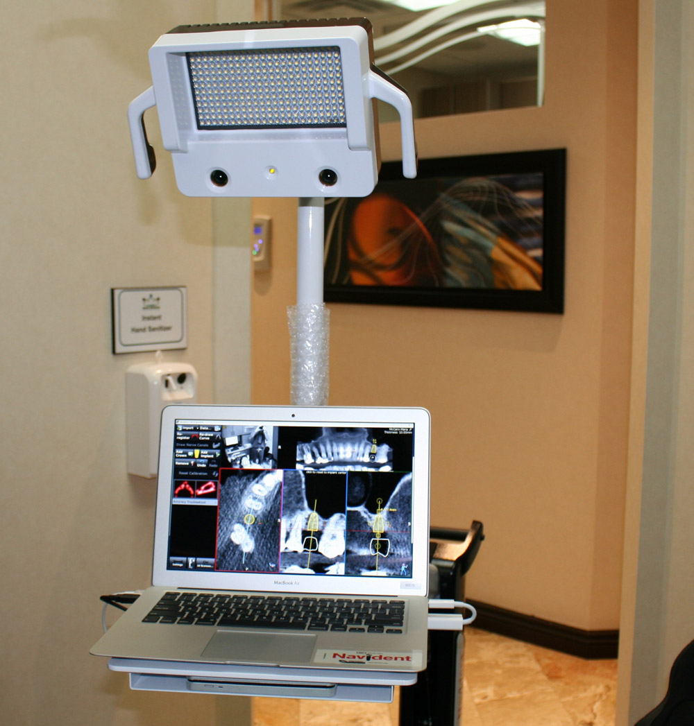
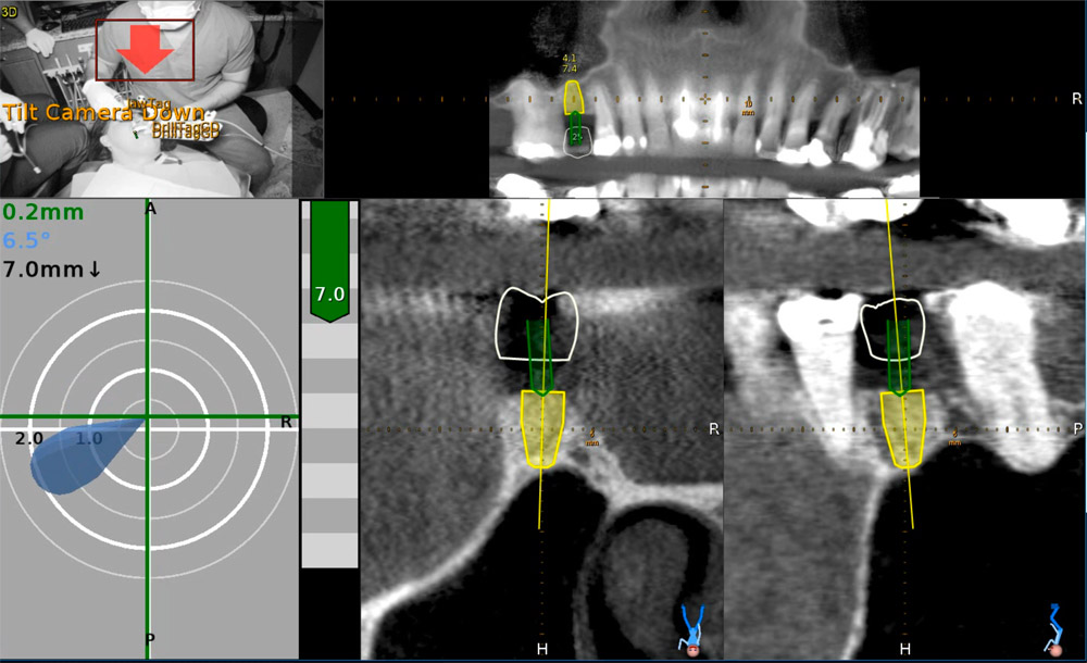
The next evolution in guided dental implant surgery comes from neurosurgery and orthopedic spine surgery where it has been used for quite some time. Claronav Inc has developed a live navigation system using optical tracking cameras (Fig 1) during implant surgery to provide the surgeon with CBCT based real-time three dimensional drill guidance during implant surgery. One of the main advantages of this Navident system (Fig1) is that dynamic navigation allows intra-operative changes to implant position in real time if any errors or anatomical complexities are noted during the surgery. The flexibility of having a guided implant placement in a digitally planned ideal location without the need for a static surgical stent and having the osteotomies live navigated on CBCT data using optical tracking is a game changer for implant dentistry. This open system also has the flexibility of using any implant system and any drill to guide placement. The case presented below showcases the flexibility of real time navigation where Straumann implant drills are used for placement of an implant with a simultaneous internal sinus lift using the Hiossen CAS-KIT drills with the Navident system.
Case Report
The patient was 57 year old healthy female that was referred to our clinic to replace the missing maxillary second premolar at the 2.5(13) site with a dental implant. The Navident workflow consists of four main sequential steps: stent fabrication, CT(computer tomography) scan with the stent and affixed CT marker in the patient’s mouth, digitally planning the implant surgery in the Navident software, and lastly completing the live guided implant surgery. One of the biggest advantages of the Navident system is that these four sequential steps can all be completed in one appointment provided the clinic has an available CBCT scanner.
The NaviStent functions as a retainer onto which the CT marker is affixed to while the patient undergoes her CBCT scan. The NaviStent is a custom single use retainer made of a thermoplastic material called Naviplast than can be heated in hot water and molded to the patient’s dentition. The stent was trimmed and the planned implant site was cut open to expose the ridge. The CT marker was then fixed to the stent by way of a thumb screw. The NaviStent with the attached CT Marker was placed into the patient’s mouth. The stent was checked for stability in the patient’s mouth. A CBCT scan was completed for the entire maxillary arch being sure to include the arm of the CT marker which contains the aluminum fiducial.
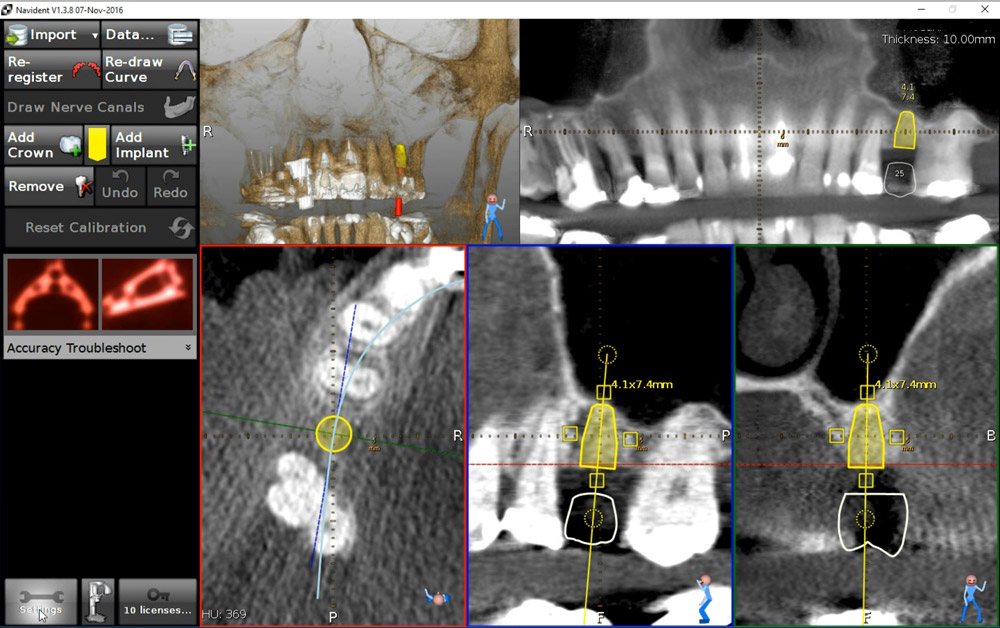
The CBCT scan was then imported into the Navident software. The Navident software automatically registers the fiducial and asks you to inspect the registration to ensure there is no malalignment. Our implant position is prosthetically determined, so our first step was to place a virtual crown at the 2.5 (13) site. The vertical height of bone from the ridge to the sinus floor was measured using the software measuring tool and found to be 7.4mm (Fig 2).
Our treatment plan involved placing a Straumann Bone Level Tapered SLActive Roxolid 4.1mm x 10mm implant as a single stage flapless approach with an internal sinus elevation. Taking advantage of the freedom of the Navident system, we were able to plan our surgery to place a Straumann dental implant and complete our internal sinus lift using the HIOSSEN CAS-KIT (Crestal Approach Sinus Kit). To control our drilling depth and use the live navigation to guide us to the sinus, a digital implant was placed in the ideal location with respect to the digital crown. This digital plan would guide us to the sinus floor for the sinus elevation and allow ideal implant placement.
Live Navigation Implant Surgery and Internal Sinus Elevation.
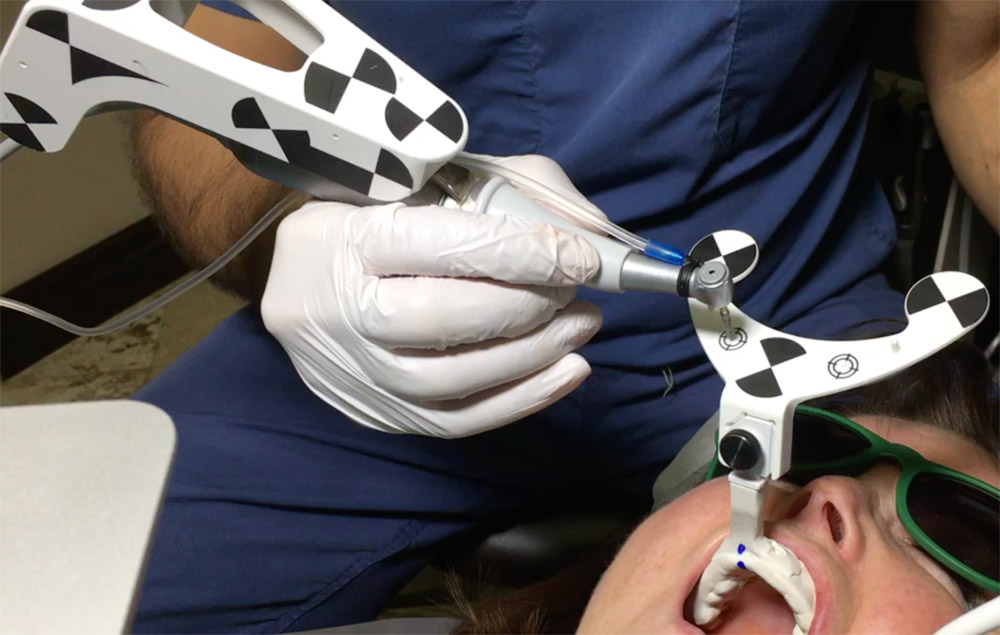
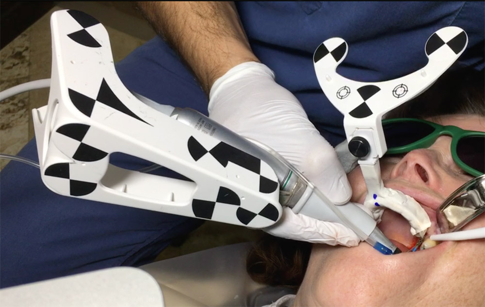
The patient was seated for the implant surgery. Local anesthetic was given. The single use JawTag was fixated to the NaviStent with the provided thumb screw. The tag adapter was mounted onto the surgical handpiece and fastened in place according to the company’s instructions. The single use DrillTag was attached to the tag adapter on the surgical handpiece. The NaviStent was placed into the patient’s mouth with the JawTag visible for the Navident camera to detect. Once the CT markers are visible by the camera, they become visible on the side panel on the monitor. The next step was to calibrate the drill axis by placing the handpiece head onto the calibration peg present on top of the JawTag. The handpiece was then rotated back and forth around the peg to register and calibrate the drill axis. The system then prompts us to calibrate the drill. The initial precision point drill was then placed onto the handpiece and calibrated by placing the drill tip into the dimple present at the center of the target on the JawTag (Fig 3). Once the drill tip was calibrated, it then became visible on the monitor against the CT image when it is placed into the surgical field. Our next step was to verify the drill tip position. This was done easily by placing the tip of the bur on a landmark in the jaw to verify accuracy of its positioning. In our case the tip of the drill was verified by placing it on the cusp tip of the neighboring tooth 2.4 (13). The drill was then brought to the surgical site (Fig 4) and the navigated drilling screen comes up which shows a Target view and cross sectional views of the CT images with the drill image visualized in its real-time position (Fig 5). The target and cross sectional views allow you to position the drill into the ideal digitally planned implant position based on the live view of the drill over the CT images.
The drilling process was started with a precision drill to punch a dimple into the bone and give us a soft tissue bleeding point. The bleeding point was then used as a marker to remove a 4mm diameter of crestal gingiva with a tissue punch. The Straumann pilot drill was then calibrated and verified on the handpiece. The 2.2 mm pilot drill was then used to drill at 800rpm to about 7mm into the osteotomy using the live navigation to guide us into the digitally planned position. The second 2.8mm drill in the Straumann Bone Level Tapered implant protocol was calibrated, verified and live navigated to the desired position at a depth of 7mm into the osteotomy.
The drills were now switched to the Hiossen CAS-KIT drills to allow removal of the cortical bone at the floor of the sinus without damaging the Schneiderian membrane. The CAS-Drill tip has an inverse conical shape that forms conical bone chip as it drills to allow it to safely elevate the sinus membrane without perforating it. The bone particles formed when drilling discharge upwards producing a membrane auto-lift function. The Hiossen CAS 3.3mm drill was used with an 8mm stopper as a back up to prevent us from forcefully pushing too deep into the sinus. The CAS drill was calibrated and verified and then live navigated to access the sinus membrane.
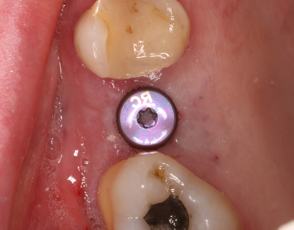
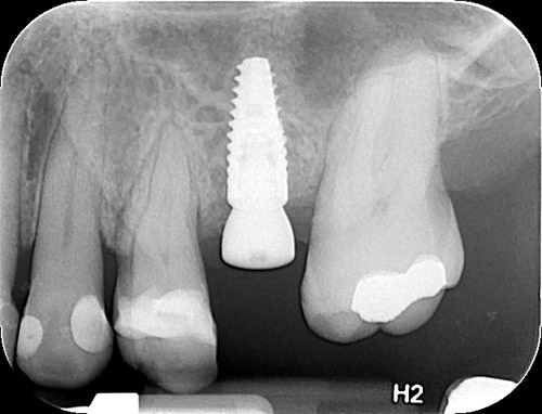
Once the membrane was exposed through the osteotomy, it was elevated using hydraulic pressure with the CAS-Kit Membrane Lifter and sterile saline. Cortical allograft chips were then gentled pushed into the void created from the membrane elevation. The jaw stent was removed and the implant was placed through the osteotomy with direct vision. The Straumann Bone Level Tapered 4.1mm x 10mm implant was placed with 50Ncm of primary stability. A healing abutment was then hand torqued in place (Fig 6). A post-operative peri-apical radiograph (Fig 7) was taken to assess the implant placement. The implant can also be live navigated into place, however it needs to be calibrated by touching the tip of the implant over the JawTag dimple, and due to the risk of contamination we chose to place it with direct vision. The company recommends placing a sterile piece of nylon over the dimple when calibrating the implant to keep the conditions of the implant sterile.
Due to the flapless live guided Navident protocol, we were able to release the patient, with no sutures required and minimal trauma to the site. The patient was prescribed anti-inflammatory analgesics and placed on a 7 day antiobiotic course. Her healing was uneventful with minimal discomfort to the area.
Conclusion
Computer guided placement of dental implants is significantly more accurate than free hand surgery. In areas of complex anatomy, computer guided navigational surgery is superior to conventional implant surgery when it comes to preventing iatrogenic injuries. This technology can contribute to considerable improvement in quality and accuracy of dental implant placement. The live real-time view of the exact position of the drill minimizes the potential risk of damage to critical anatomic structures. The optical tracking system seems to be more accurate and have more flexibility during surgery but does require more training to develop hand eye coordination for using the system. However once mastered, this new system can improve on accuracy of surgery, reduce surgeon anxiety, improve patient confidence, and work as a powerful marketing tool for your practice.
About Naheed Mohamad
 Dr. Naheed Mohamed received his Honours Bachelor of Science degree from the University of Toronto. After a year of periodontal research at Mount Sinai Hospital, he attended dental school at Boston University and completed his Doctor of Dental Medicine degree. Graduating from dental school with magna cum laude and the American Academy of Periodontology Dental Student of the Year Award for achievement in Periodontics, Dr. Mohamed further pursued his studies at Case Western Reserve University in Cleveland to complete his specialty training in Periodontics. During his residency he pioneered research in an autologous blood derived material called platelet-rich fibrin and its numerous clinical applications; earning his Masters Degree. Dr. Mohamed is a board certified specialist in the United States and Canada attaining his Diplomate status by the American Board of Periodontology and Fellow of the Royal College of Dentists of Canada. Dr. Mohamed currently maintains a private practice and actively lectures about innovations in Periodontics and Implant surgery.
References
1. Rosenfeld AL, Mandelaris GA, Tardieu PB. Prosthetically directed implant placement using computer software to ensure precise placement and predictable prosthetic outcomes. Part 1: diagnostics, imaging, and collaborative accountability. Int J Periodontics Restorative Dent. 2006;26(3):215-221.
2. Buser D, Martin W, Belser UC. Optimizing esthetics for implant restorations in the anterior maxilla: Anatomic and surgical considerations. Int J Oral Maxillofac Implants. 19:(suppl):43-61
3. Jung RE, Schneider D, Ganeles J, Wismeijer D, Zwahlen M, Hammerle CH, & Tahmaseb A. (2009) Computer Technology applications in surgical implant dentistry: a systematic review. International Journal of Oral and Maxillofacial Implants 24(suppl.):92-109.
4. Cassetta M, Stefanelli LV, Giansanti M, et al. Depth deviation and occurrence of early surgical complications or unexpected events using a single stereolithographic surgi-guide. Int J Oral Maxillofac Surg. 2011;40(12):1377-1387.
5. Somogyi-Ganss E, Holmes HI, Jokstad A. Accuracy of a novel prototype dynamic computer-assisted surgery system. Clin. Oral Impl. 2014 May 19. doi: 10.1111/clr.12414
6. Accuracy of image-guided implantology. Brief J, Edinger D, Hassfeld S, Eggers G. Clin Oral Implants Res. 2005 Aug;16(4):495-501.
7. Computer-assisted navigational surgery enhances safety in dental implantology. Ng FC, Ho KH, Wexler A. Ann Acad Med Singapore. 2005 Jun;34(5):383-8
8. Clinical advantages of computer-guided implant placement: a systematic review. Hultin M, Svensson KG, Trulsson M. Clin Oral Implants Res. 2012 Oct;23 Suppl 6:124-35
9. Computer-aided manufacturing technologies for guided implant placement. Neugebauer J, Stachulla G, Ritter L, Dreiseidler T, Mischkowski RA, Keeve E, Zöller JE. Expert Rev Med Devices. 2010 Jan;7(1):113-29. doi: 10.1586/erd.09.61. Review.